
Method of operating a plumbing system

a technology of plumbing system and plumbing system, applied in the field of plumbing system operation, can solve the problems of substantial water loss, wasteful hot water line thermal energy, and wasteful water and energy loss in commercial establishments, and achieve the effect of managing water usage, reducing water waste and energy was

Inactive Publication Date: 2005-01-13
ACT DISTRIBUTION
View PDF4 Cites 52 Cited by
  • Summary
  • Abstract
  • Description
  • Claims
  • Application Information

AI Technical Summary

Benefits of technology

[0003] In some homes and many commercial establishments, such water loss is reduced by providing plumbing systems which continuously circulate hot water from a hot water source to the fixture and back to the hot water source. In this arrangement, a supply of hot water is always adjacent to a plumbing fixture despite the remote position of the hot water source.
[0004] While this arrangement reduces water loss, it is not energy efficient because the array of pipes interconnecting the plumbing fixtures and the hot water source provide an enormous surface area for thermal radiation. In addition, the electrical expense of running a circulation pump may be prohibitive in view of the latest energy costs.
[0006] Hot water demand systems have been developed, such as for example, set forth in U.S. Pat. Nos. 5,277,119, 5,385,161 and 5,829,475. The system described in these patents significantly reduces water and energy loss through the use of a demand control. That is, whether a recirculation conduit is utilized or a cold water line is utilized for circulation of water, such circulation is initiated only upon demand by a user. Such demand may be a manual switch, temperature sensor or the like.
[0010] Preferably, the method according to the present invention includes reiterating the hereinabove noted steps for providing updated patterns of pump activity, thus enabling pump activation to be continually changed in response to usage of the system.
[0011] More particularly, the present invention may also include analyzing the determined patterns for potential problems, such potential problems including, but not limited to identifying a leak in the plumbing system, excess running of the pump, and non-seasonal changes in a relationship between hot and cold water use. Also, temperature sensors may be used to detect freezing temperature and circulating water to avoid damage.
[0012] Thus, the present invention provides a method for managing water usage and reducing water waste and energy waste which is dependent upon actual use of the plumbing system.

Problems solved by technology

In the home, a considerable amount of thermal energy may be wastefully dissipated from hot water lines which provide hot water to plumbing fixtures, such as domestic wash basins, showers, dishwashers, washing machines, etc.
Commercial establishments also experience wasteful water and energy losses due to continuously running recirculation systems or for timing or delivering hot water to numerous fixtures, such as in hotels and the like.
In both home and commercial establishments, if water is allowed down the drain while waiting for hot water to be delivered to the fixture from a remote hot water source, a substantial water loss may occur.
While this arrangement reduces water loss, it is not energy efficient because the array of pipes interconnecting the plumbing fixtures and the hot water source provide an enormous surface area for thermal radiation.
In addition, the electrical expense of running a circulation pump may be prohibitive in view of the latest energy costs.
While such insulation slows the dissipation of heat, no savings occur over an extended period of time in non-circulating systems because intermittent use of hot water through the lines still allows hot water to cool to ambient temperatures.

Method used


Image

  • Method of operating a plumbing system
  • Method of operating a plumbing system
  • Method of operating a plumbing system

Examples


Embodiment Construction

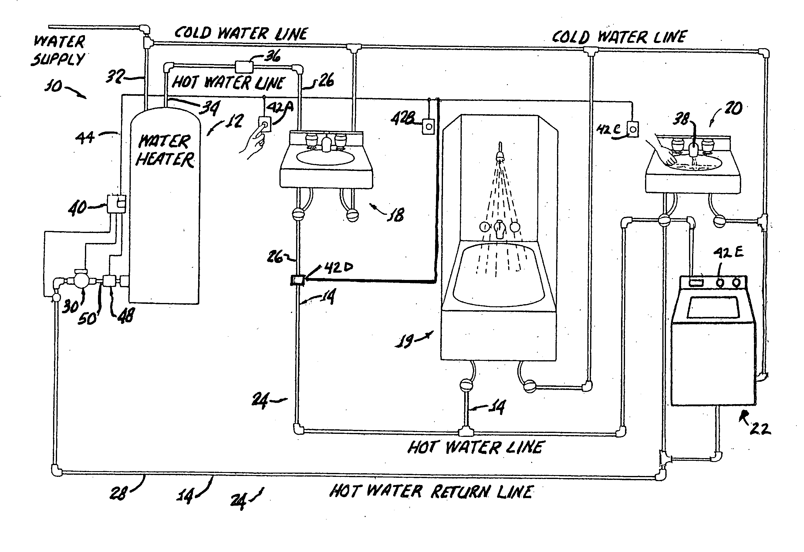
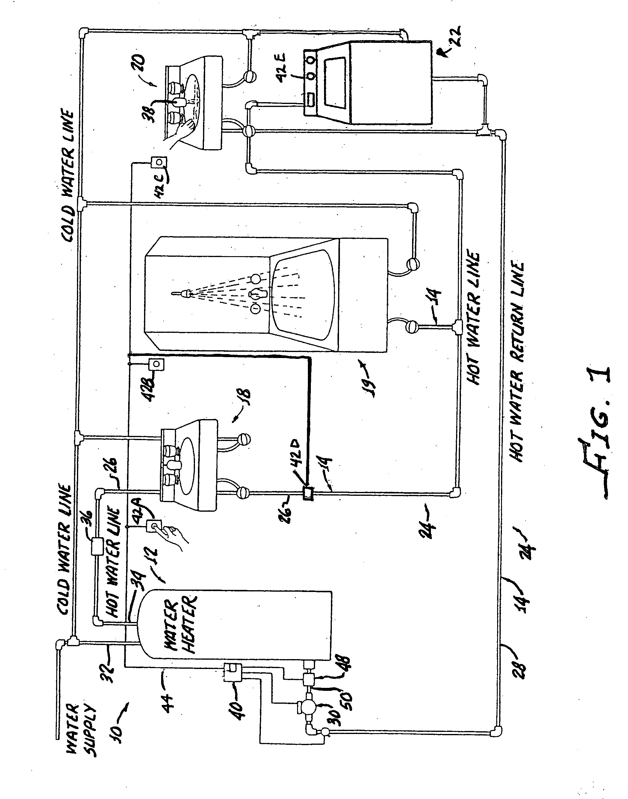
[0018] With reference to FIG. 1, a hot water recirculation system 10 is shown in accordance with the present invention. The system 10 generally comprises a hot water source, for example a water heater 12, such as for example, a gas, oil, solar or electric tanks or tankless heater, interconnected by means of pipes 14 with plumbing fixtures 18, 19, 20, 22, said pipes providing conduit means for enabling circulation of hot water from said hot water source 12 to each plumbing fixture 18, 19, 20 and return to the hot water source 12. The pipes 14 are thus in fluid communication with the hot water source 12 and the plumbing fixtures 18, 19, 20 in such a way as to establish a hot water loop 24.

[0019] More particularly, the pipes 14 may be comprised of a hot water supply line 26 which provides means for transferring hot water from the water heater 12 to each of the fixtures 18, 19, 20, 22 and a separate hot water return line 28 which provides means for enabling recovery of hot water in the...


PUM


Abstract

A method of operating a plumbing system having a circulating pump includes sensing activation of the pump and recording for each sensed activation at least one parameter selected from the group consisting of date, day of the week, start time, duration of pump activation, hot water flow, and temperature and cold water flow in temperature. The parameters are analyzed to determine a pattern of pump activity and thereafter the pump is activated in accordance with the determined pattern.

Description

[0001] The present invention is generally directed to plumbing systems and more particularly to operation of plumbing systems to attain high thermal and economic efficiency. [0002] Water and energy conservation is of utmost importance. This is true for both home and commercial plumbing systems. In the home, a considerable amount of thermal energy may be wastefully dissipated from hot water lines which provide hot water to plumbing fixtures, such as domestic wash basins, showers, dishwashers, washing machines, etc. Commercial establishments also experience wasteful water and energy losses due to continuously running recirculation systems or for timing or delivering hot water to numerous fixtures, such as in hotels and the like. In both home and commercial establishments, if water is allowed down the drain while waiting for hot water to be delivered to the fixture from a remote hot water source, a substantial water loss may occur. [0003] In some homes and many commercial establishment...

Claims


Application Information

Patent Timeline
IPC IPC(8): F24D17/00F24D19/10
CPCF24D17/0078F24D19/1051F24D19/1012
Inventor ACKER, LARRY K.
Owner ACT DISTRIBUTION
Learn More