Compact and efficient three dimensional antennas

Inactive Publication Date: 2005-01-13
HANDELSMAN DAN G
View PDF10 Cites 20 Cited by
  • Summary
  • Abstract
  • Description
  • Claims
  • Application Information

AI Technical Summary

Benefits of technology

[0040] Such an electrical loop length is advantageous since, at frequencies just below the high-impedance half wave point, the radiation resistance (Rrad) is high while the reactance is inductive. The value of the capacitor may be adjusted to attain any value of Rrad that is desired. The inductive reactance may then be tuned out by a high-Q capacitor placed in series with the feedpoint.
[0041] The high Rra

Problems solved by technology

If, however, such symmetrical loops are operated at frequencies below those where the perimeter is a half-wavelength, they have very low radiation resistance (Rrad) and inductive re

Method used


Image

  • Compact and efficient three dimensional antennas
  • Compact and efficient three dimensional antennas
  • Compact and efficient three dimensional antennas

Examples


example 1

[0154] In one embodiment, the external loop is a square having a perimeter of 4.08 m. Inside it, is placed another radiator which is 0.2 m from the fed loop.

[0155] This radiator contains a Cparallel of 146 pF. This places the R=50 ohm point at 7 MHz. The reactance (X) is 1,952 ohms and this can be tuned out by a Cseries of 11.34 pF.

[0156] The gain, at a TOA of 30 degrees is −7.5 dBi. Depending on how well the simple reference compact loop in FIG. 1 is constructed and matched, this embodiment of the square loop, with an extra radiator has a greater gain of 2.5 to 6.5 dB.

[0157] Further studies and confirmation of modeling predictions with measurements on prototype antennas led to the following preferred embodiment:

example 2

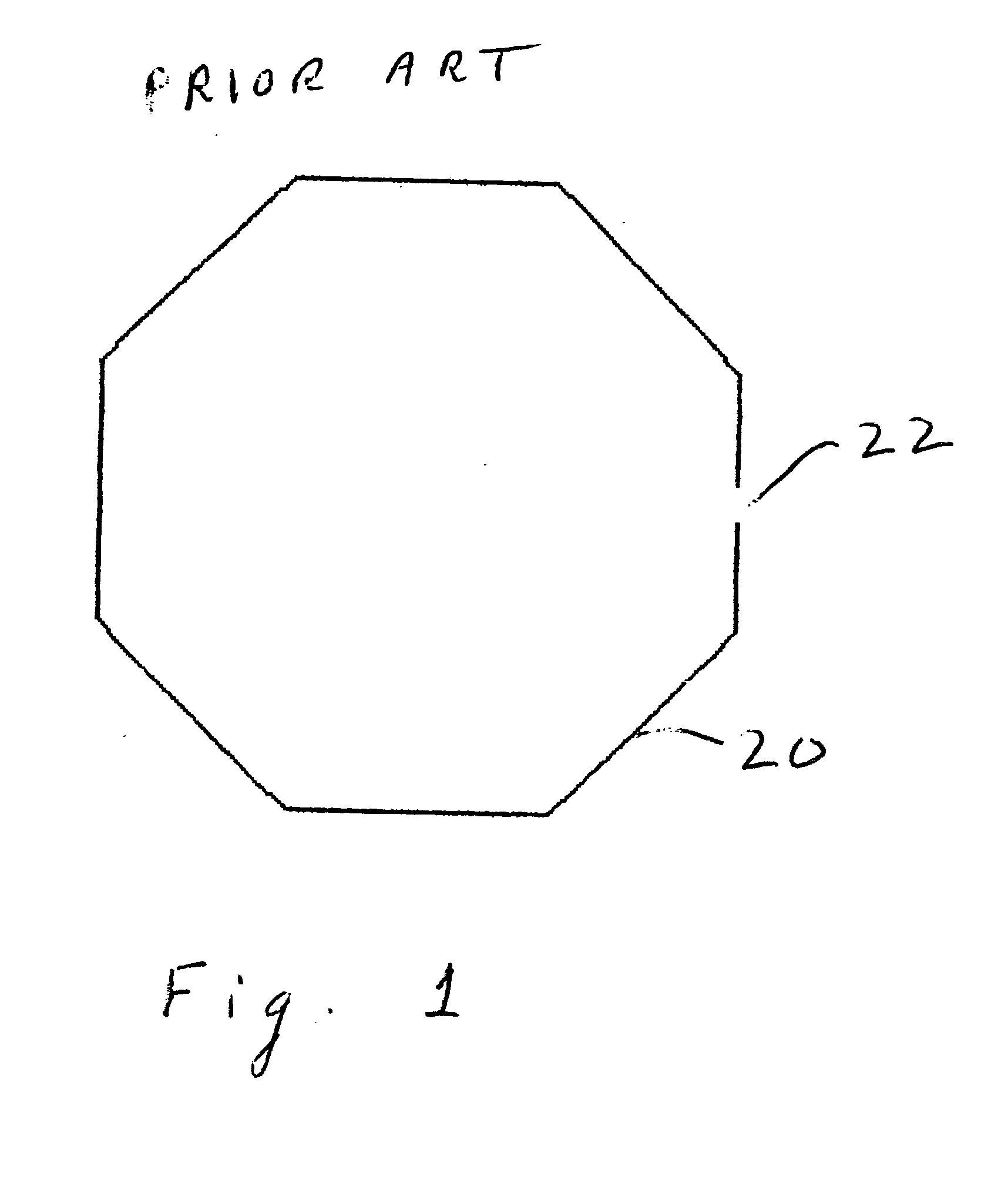
[0158] This is an octangonal loop with an added radiator of the type illustrated in FIG. 18.

[0159] By choosing the appropriate value for the variable capacitance, the antenna is made to tune (that is to have an input resistance (Rin) of 50 ohms) over a frequency range exceeding 7:1. The parallel capacitor 124 moves the frequency where the antenna is a half electrical wavelength in size. The greater the capacitance, the lower the frequency. It is a simple task to add sufficient capacitance to reach the Rin=50 ohm point anywhere in the tuning range of the antenna. Since the antenna's reactance (X) is always positive a Cseries at the feedpoint has to be provided in order to tune out the reactance.

[0160] The Rrad of such an antenna is many orders of magnitude greater than the Rrad of a simple Compact Loop lacking the added design embodiment.

[0161] In this embodiment, the antenna in question, a 4.08 m perimeter octagonal compact loop, is identical to the simple reference compact loop ...


PUM


Abstract

A volumetrically compact and efficient antenna, with a high radiation resistance and low losses, that can be designed for any frequency, and which has a gain within 1 dB of that of a full-sized vertical monopole radiator or, in its horizontally polarized form, within 2 dB of that of a horizontally polarized half-wave dipole. One embodiment is a rectangle, with short radiators and long interconnecting wires, which has been folded back on itself in a manner that results in a square configuration (when viewed from the top) and brings the two radiating wires into close proximity. Only a single port need be fed. Linear loading sections, such as stubs, serrations and helically wound interconnecting wires can be used to electrically lengthen the antenna, while keeping physical dimensions small. Capacitive loading sections are also used. Two unequal-sized rectangular loops may be joined onto each other, to provide an additional radiating element.

Description

BACKGROUND OF THE INVENTION [0001] 1. Field of the Invention [0002] The present invention relates to antennas. More particularly, it relates to three-dimensional, volumetrically compact antennas of high efficiency. It also relates to compact loop antennas of high efficiency, high gain, and the ability to be tuned over a very wide frequency range. [0003] 2. Prior Art [0004] There are various types of antennas that are known in the art. These antennas include the full-wave loop, which can be of any-shaped perimeter from a triangle, square, rectangle, to a polygon with “n”-sides, culminating in a circle. Other such antennas involve operating the above loops at fractions of their resonant frequencies and are therefore small in size with respect to wavelength. [0005]FIG. 1 illustrates one such prior art antenna; a symmetrical octagonal loop 20, which can be full-sized or compact in size depending on the frequency of operation. [0006] Such loop antennas can be fed anywhere on their perime...

Claims


Application Information

Patent Timeline
IPC IPC(8): H01Q11/14H01Q11/18
CPCH01Q11/18H01Q11/14
Inventor HANDELSMAN, DAN G.
Owner HANDELSMAN DAN G
Why Eureka
Try Eureka