Display apparatus, display method and method of manufacturing a display apparatus

a technology of display apparatus and display method, which is applied in the direction of diagnostic recording/measuring, identification means, instruments, etc., can solve the problems of inability to properly correct the light emission of the el element, inevitable lowering of image quality, etc., and achieves the effect of reducing the occurrence of color spots

Inactive Publication Date: 2005-01-13
ELEMENT CAPITAL COMMERCIAL CO PTE LTD
View PDF3 Cites 136 Cited by
  • Summary
  • Abstract
  • Description
  • Claims
  • Application Information

AI Technical Summary

Benefits of technology

[0013] In the case where an image is displayed by a plurality of pixels arranged in two dimensions, it is possible to make the brightness of the emitted light uniform for each light emitter in the two dimensions.
[0014] When images are displayed in color, it can be possible to make the brightness of the emitted light uniform and to also suppress the occurrence of color spots.
[0015] In addition, it is possible to f

Problems solved by technology

However, when such organic EL display apparatuses are constructed with a large screen, there is an inevitable lowering in image quality due to fluctuations in brightness between the light emitters of the respective pi

Method used


Image

  • Display apparatus, display method and method of manufacturing a display apparatus
  • Display apparatus, display method and method of manufacturing a display apparatus
  • Display apparatus, display method and method of manufacturing a display apparatus

Examples


Embodiment Construction

[0019] An embodiment of the invention will now be described with reference to the attached drawings. It should be noted that the present embodiment relates to a case where the invention has been applied to an organic EL display apparatus.

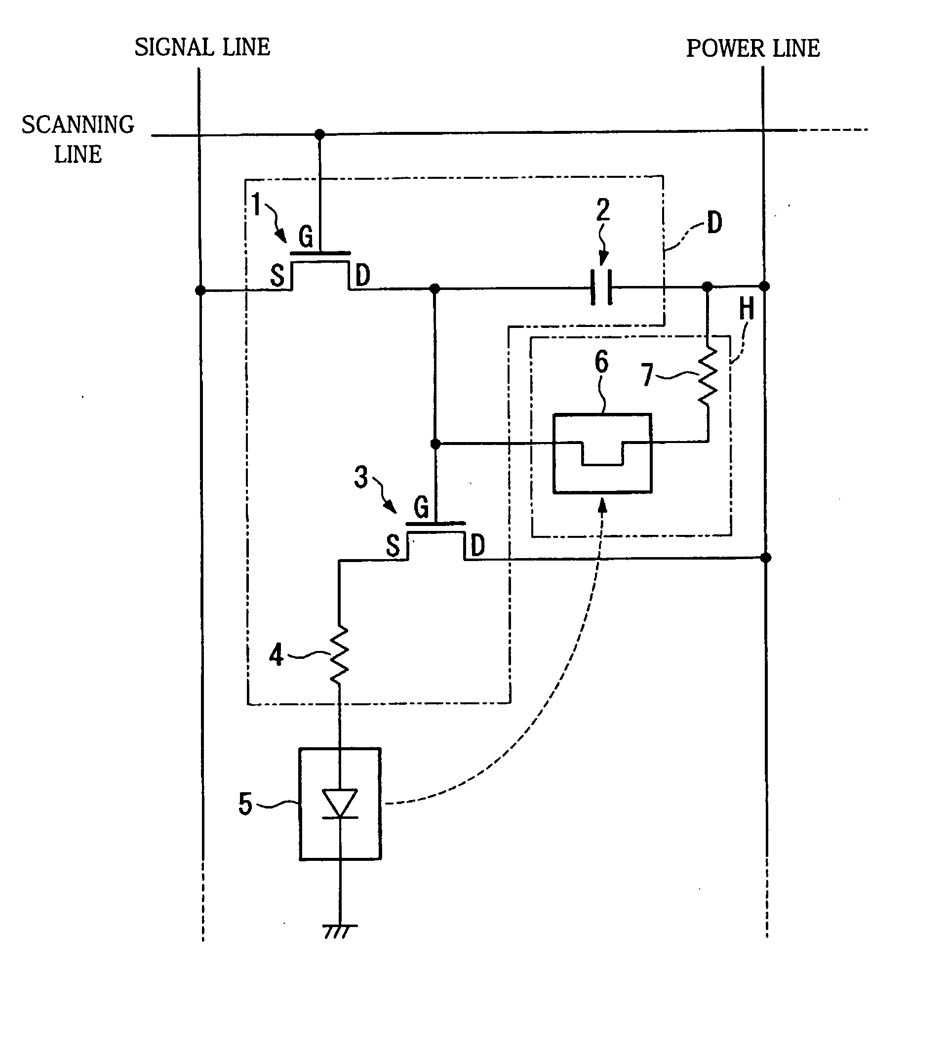
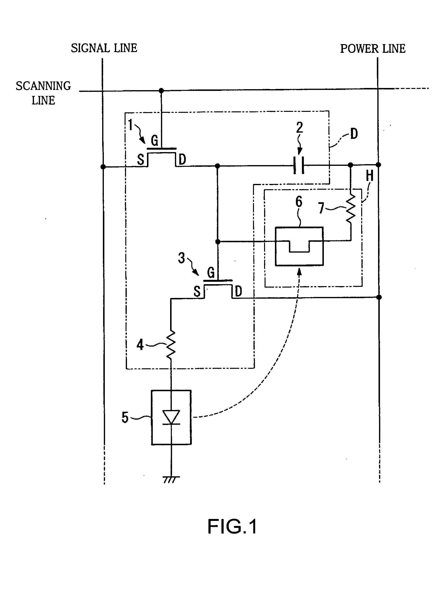
[0020]FIG. 1 is an exemplary circuit diagram showing the electrical configuration of a main part (pixels) of this organic EL display apparatus. In FIG. 1, reference numeral 1 designates a first transistor, 2 a capacitor (data voltage holding capacitor), 3 a second transistor, 4 a first resistor, 5 a light emitting organic EL element (light emitter), 6 a light receiving organic EL element (light receiver), and 7 a second resistor. Out of these components, the light receiving organic EL element 6 and the second resistor 7 compose a correction circuit H, while the first transistor 1, the capacitor 2, the second transistor 3, and the first resistor 4 compose a driving circuit D.

[0021] These components construct one pixel in the present organic EL disp...


PUM


Abstract

To precisely reduce fluctuations in brightness of respective light emitters when displaying an image by having a plurality of light emitters emit light, and thereby improve image quality. A display apparatus can be made of an arrangement of a plurality of pixels respectively composed of a predetermined driving circuit and a light emitter that emits light when driven by the driving circuit. Each pixel can include a correction circuit that detects an amount of light for the light emitter using a light receiver made of the same type of material as the light emitter and implements feedback control over the driving circuit based on a detection result.

Description

BACKGROUND OF THE INVENTION [0001] 1. Field of Invention [0002] The present invention relates to a display apparatus and a display method. [0003] 2. Description of Related Art [0004] As is well known, much research and development has been conducted into organic electroluminescent (EL) display apparatuses due to their promise as next generation display apparatuses. Such organic EL display apparatuses use organic EL materials as the light emitter composing each pixel, and an active matrix method is normally used as the driving method for such organic EL materials. [0005] However, when such organic EL display apparatuses are constructed with a large screen, there is an inevitable lowering in image quality due to fluctuations in brightness between the light emitters of the respective pixels. For example, in the case of a large color organic EL display apparatus, not only bright spots but color spots appear in the entire display, so that in order to construct organic EL display apparatu...

Claims


Application Information

Patent Timeline
IPC IPC(8): G09F9/00H01L51/50G09F9/30G09G3/20G09G3/30G09G3/32G09G5/00H01L27/32H05B33/14H05B44/00
CPCG09G3/3233G09G2300/0819G09G2360/148G09G2300/088G09G2320/045G09G2300/0842B60N2/002A61B5/6893G06Q50/22
Inventor MIURA, HIROTSUNA
Owner ELEMENT CAPITAL COMMERCIAL CO PTE LTD
Why Eureka
Try Eureka