Light source device with optical guiding member and planar light source device employing same

a light source device and optical guiding member technology, applied in the direction of instruments, mechanical devices, lighting and heating apparatus, etc., can solve the problems of insufficient uniform illumination of the planar light source device, limited lighting characteristics of ordinary leds, and higher power consumption, so as to achieve high uniform illumination and low power consumption

Inactive Publication Date: 2005-01-13
HON HAI PRECISION IND CO LTD
View PDF4 Cites 43 Cited by
  • Summary
  • Abstract
  • Description
  • Claims
  • Application Information

AI Technical Summary

Benefits of technology

[0007] An object of the present invention is to provide a planar light sour

Problems solved by technology

However, the lighting characteristics of ordinary LEDs are limited, and the uniformity of illumination of the planar light source device may not be sufficient.
The number

Method used


Image

  • Light source device with optical guiding member and planar light source device employing same
  • Light source device with optical guiding member and planar light source device employing same
  • Light source device with optical guiding member and planar light source device employing same

Examples


first embodiment

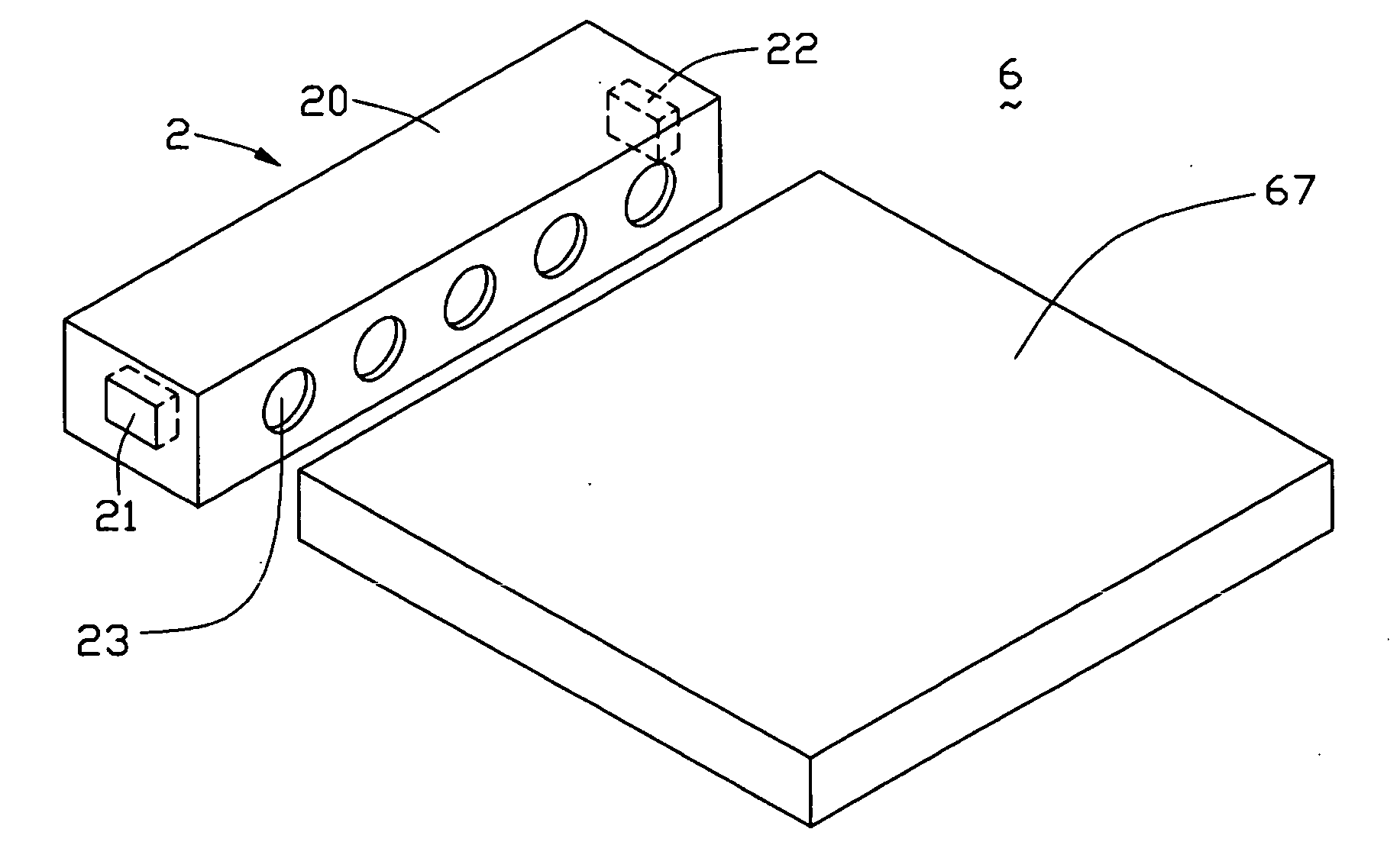
[0017] Referring to FIG. 1, a planar light source device 6 according to the present invention includes a transparent plate-shaped LGP 67 and a light source device 2. The light source device 2 is arranged adjacent to a light incident surface (not labeled) of the LGP 67, for providing illumination thereto.

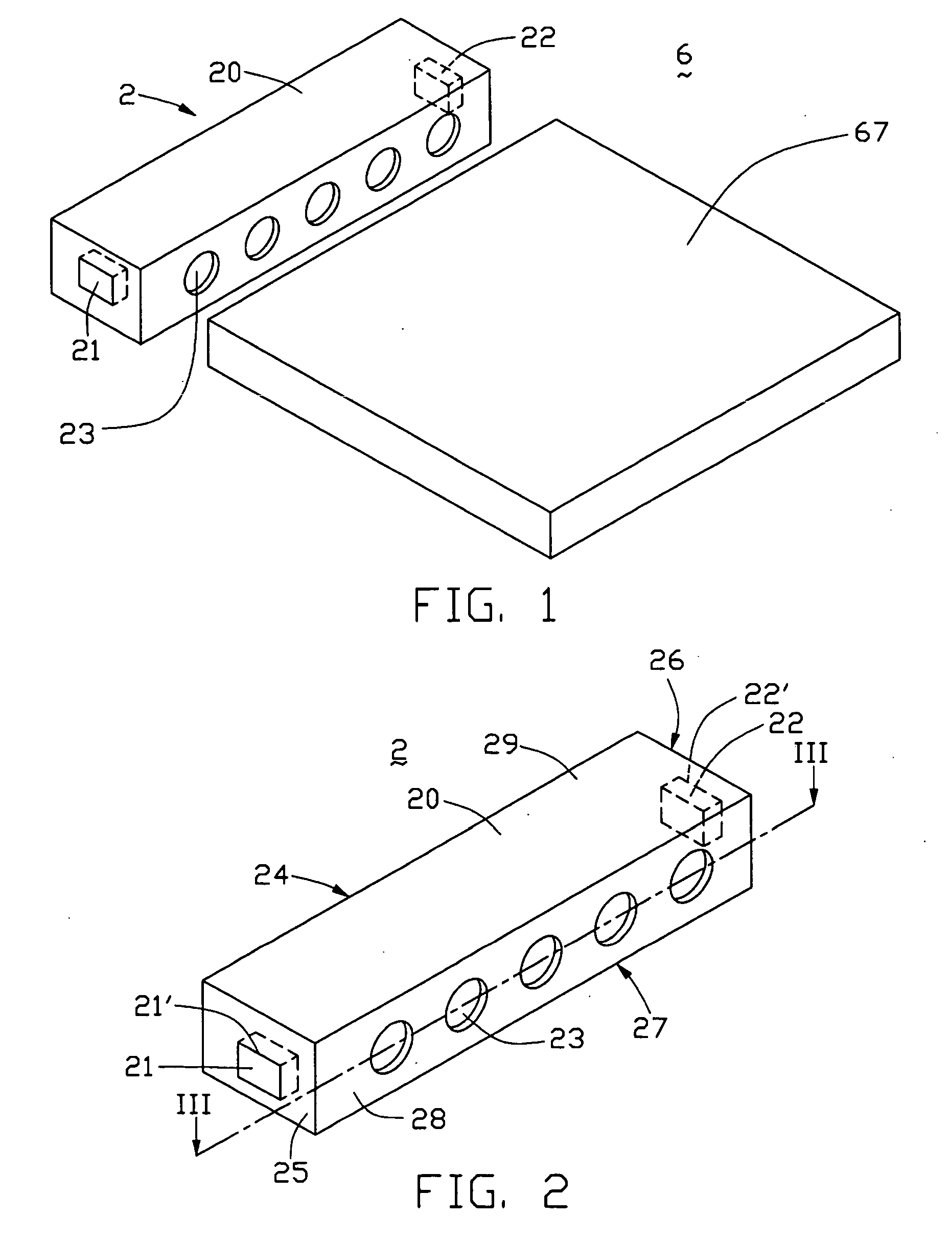
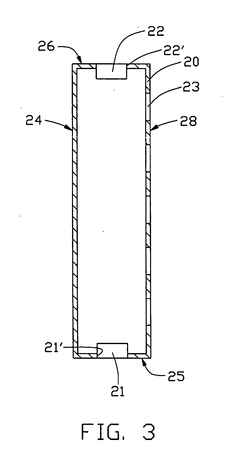
[0018] Referring to FIGS. 2 and 3, the light source device 2 includes an optical guiding member 20 and two LEDs 21, 22. The optical guiding member 20 functions as a linear light source, and is substantially a hollow box. The optical guiding member 20 comprises a light-emitting surface 28, a back surface 24 opposite to the light-emitting surface 28, a bottom surface 27 adjoining the light-emitting surface 28, and a upper surface 29 opposite to the bottom surface 27. The optical guiding member 20 further comprises two opposite side surfaces 25, 26 adjoining the above-described surfaces 24, 27, 28, 29, and an internal light reflective surface (not labeled). A plurality of uniform, align...

second embodiment

[0021] Referring to FIG. 4, in a planar light source device 3 according to the present invention, two LEDs 31, 32 are fixed in a back surface 34 of an optical guiding member 30. Light rays emitted by the LEDs 31, 32 are guided by the optical guiding member 30, and emit from a light-emitting surface 38 through a plurality of through holes 33 thereof.0

third embodiment

[0022] Referring to FIG. 5, a light source device 4 according to the present invention includes an optical guiding member 40, and two LEDs 41, 42. The optical guiding member 40 is substantially a hollow arch-shaped box, which comprises a planar light-emitting surface 48, an arch-shaped back surface 44 adjoining the light-emitting surface 48, and two opposite side surfaces 45, 46. The optical guiding member 40 further comprises an internal light reflective surface (not shown). A plurality of uniform, aligned through holes 43 is defined in the planar light-emitting surface 48 of the optical guiding member 40. The through holes 43 function as light exits. Two openings (not labeled) are defined in the side surfaces 45, 46 of the optical guiding member 40 respectively. The LEDs 41, 42 are fixed in the openings respectively, such that exposed faces of the LEDs 41, 42 are coplanar with the side surfaces 45, 46 respectively.

[0023] Further alternative embodiments of the planar light source d...


PUM


Abstract

A light source device (2) and a planar light source device (6) for a liquid crystal display device. The planar light source device includes a light source device and a light guide plate (67). The light source device includes a light-emitting element (21) and an optical guiding member (20) having a reflective surface. The reflective surface receives light rays emitted by the light-emitting element (21), and guiding the light rays out from a plurality of generally aligned through holes (23) defined in a front light-emitting surface (28) of the optical guiding member. The light guide plate has a light incident surface being adjacent to the light source device. The planar light source device can diminish greatly possible dark regions on the light-emitting surface of the light guide plate and provide uniform illumination for an LCD.

Description

BACKGROUND OF THE INVENTION [0001] 1. Field of the Invention [0002] The invention generally relates to a light source device and a planar light source device used in a liquid crystal display (LCD) device. [0003] 2. Prior Art [0004] In general, an LCD device has the advantages of thinness, light weight, and low power consumption. For this reason, LCD devices are widely utilized in various types of electronic equipment, from pocket calculators to large-scale office automation equipment. [0005] Conventionally, planar light source devices are designed for use in an LCD device for backlighting purposes. The planar light source device generally includes a light guide plate (LGP) and at least one light source. The LGP has at least one light incidence surface, and one light-emitting surface. In operation, light rays emitted by the light source(s) enter the LGP through the light incident surface(s) thereof, and are guided through the LGP to emit from the light-emitting surface. Each light so...

Claims


Application Information

Patent Timeline
IPC IPC(8): F21V8/00
CPCG02B6/0028G02B6/0096G02B6/0031
Inventor LEE, CHUN-YUTSAI, MING-CHIANGJIANG, TSUNG-WEI
Owner HON HAI PRECISION IND CO LTD
Why Eureka
Try Eureka