
Method and system for repairing endosseous implants, such as with a bone graft implant

a technology of endosseous implants and bone grafts, which is applied in the field of endosseous implant repair methods and systems, can solve the problems of mechanical failure of an original secure edi, unsatisfactory mechanical support of the edi, and observed loosening of the endosseous implan

Inactive Publication Date: 2005-01-13
THERICS
View PDF29 Cites 27 Cited by
  • Summary
  • Abstract
  • Description
  • Claims
  • Application Information

AI Technical Summary

Problems solved by technology

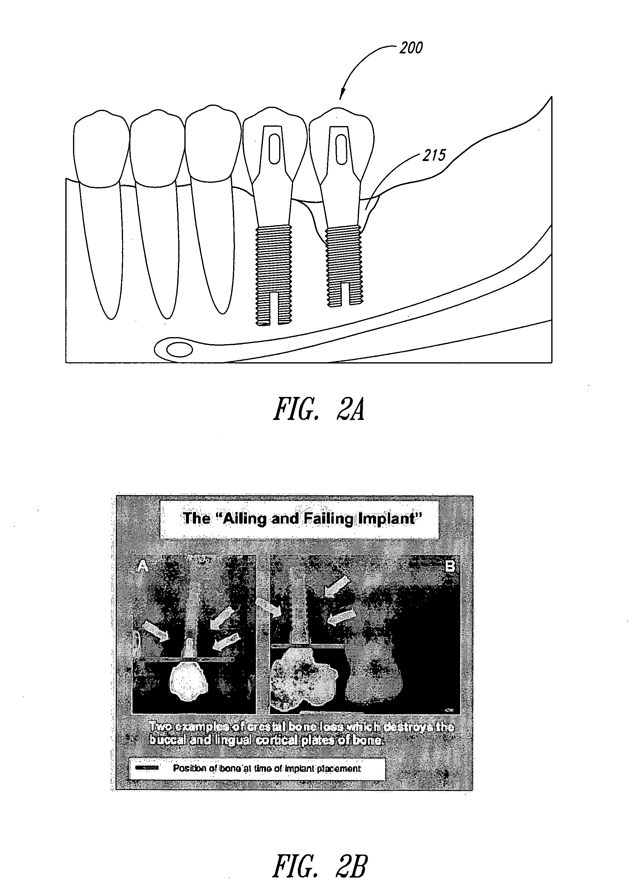
However, in a small fraction of cases, an endosseous implant has been observed to loosen with the passage of time, due to deterioration or resorption of bone immediately adjacent to the implant base.
Loss of support from some portion of the adjacent bone can lead to loosening and mechanical failure of an originally secure EDI.
The X-rays in FIG. 2B show the bone adjacent to the endosseous implants deteriorated or missing, leaving the EDI with inadequate mechanical support.
The success rate of this procedure has been erratic and low.
In still other cases, the filler material has become integrated with bone but has later resorbed, resulting in a re-occurrence of the original problem.
Because the autograft or allograft has been solid, such a procedure has avoided the migration problem experienced with formable material, but the bone installed in such a procedure has still been subject to possible resorption, which would represent a re-occurrence of the original problem.
As is usually the case with such sources of bone material, the use of allograft bone has introduced the possibility of disease transmission from the donor, and the use of an autograft has involved the extra inconvenience, pain and expense of the surgery at a second site in the same patient for harvesting of bone.
This yields inconsistent preparation of the recess due to the difficulty accessing portions between the implant base and existing teeth.

Method used


Image

  • Method and system for repairing endosseous implants, such as with a bone graft implant
  • Method and system for repairing endosseous implants, such as with a bone graft implant
  • Method and system for repairing endosseous implants, such as with a bone graft implant

Examples


Embodiment Construction

[0031] Method of Installing a Bone Graft or Other Filler Using a Bone Graft Profiler Tool

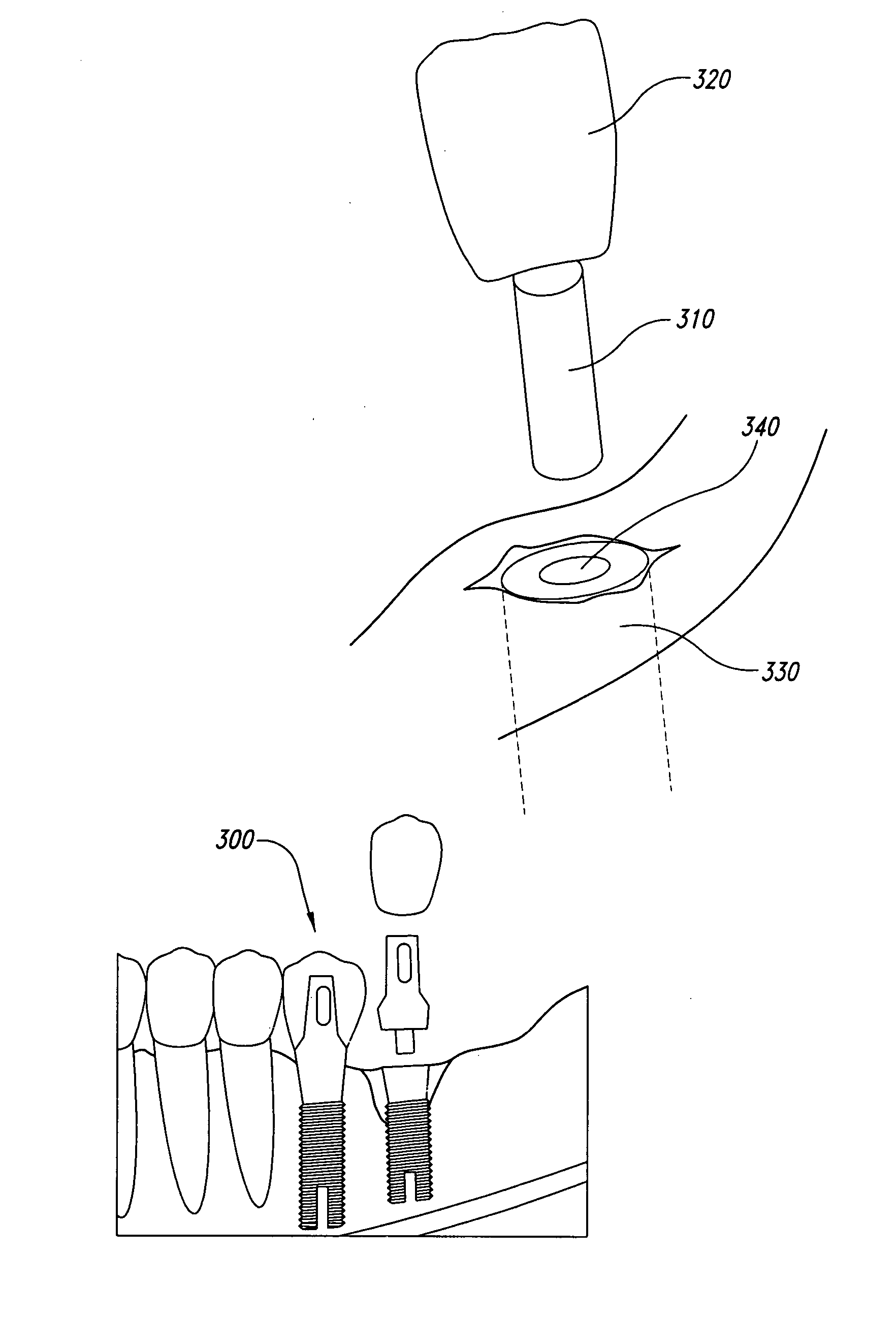
[0032] One aspect of the present invention is a method of repairing an ailing / failing endosseous implant using a bone graft profiler tool. The method of repair is illustrated in FIGS. 3 through 11. As illustrated in FIG. 4, an endosseous implant 300 already installed in a patient may comprise an existing implant base 330 which is already installed in the patient's maxilla or mandible, and an abutment post 310 which engages securely with the implant base 330, and a tooth prosthesis 320 which attaches to the abutment post 310. The tooth prosthesis 320 may be either a single tooth (as illustrated) or a part of a larger prosthesis structure, such as a bridge, which may be supported either by one abutment post. (as illustrated) or by more than one abutment post.

[0033] The first step of the method of the present invention may be to remove the existing tooth prosthesis 320 from the abutment post 310 ...


PUM


Abstract

A bone graft that is made at least partially of synthetic material and is of a suitable shape to fill a recess around the base of an ailing / failing endosseous implant. The bone graft may be pre-manufactured in the suitable shape. The invention also comprises a method of installing either such a bone graft or any other type of filler. The invention also comprises various types of bone graft profiler tools suitable for preparing the recess, and optionally an alignment post to assist in the use of the bone graft profiler tool(s). The dimensions of the bone graft profiler tool(s) and the dimensions of the bone graft and the dimensions of the alignment post may be chosen to have defined geometric relationships with respect to each other, with respect to the dimensions of the existing implant base, and with respect to the extent of bone deterioration at a particular implant site in a particular patient.

Description

BACKGROUND OF THE INVENTION [0001] 1. Field of the Invention [0002] The present invention relates to a method and system for repairing endosseous implants, and more particularly, to a bone graft for such repair, method of manufacturing the bone graft, a bone graft profiler tool, an alignment post and a system for installing the same. [0003] 2. Description of the Related Art [0004] An endosseous implant (EDI) comprises an implant base that is installed directly into the bone of a patient's mandible or maxilla, an abutment post that engages the implant base, and a tooth prosthesis that attaches onto the abutment post. Basic techniques of implant dentistry are described in “An Illustrated Guide to Understanding Dental Implants,” by Scott D. Ganz, D.M.D. (1993). Implant dentistry has become a practical restorative method with a high reliability and success rate. However, in a small fraction of cases, an endosseous implant has been observed to loosen with the passage of time, due to dete...

Claims


Application Information

Patent Timeline
Patent Type & Authority Applications(United States)
IPC IPC(8): A61C8/00
CPCA61C8/0006A61C8/00
Inventor GANZ, SCOTT D.MATERNA, PETER A.STIKELEATHER, ROGER C.BRADBURY, THOMAS J.
Owner THERICS
Learn More