In-band-on-channel broadcast system for digital data

a digital data and modulation system technology, applied in the field of modulation techniques, can solve the problems of system constraints, signal carrying such a data stream cannot be transmitted in the bandwidth available in the fm broadcast signal, and the bandwidth required for the signal cannot be used, so as to achieve the effect of high data rate digital signal

Inactive Publication Date: 2005-01-13
THOMSON LICENSING SA
View PDF10 Cites 9 Cited by
  • Summary
  • Abstract
  • Description
  • Claims
  • Application Information

AI Technical Summary

Benefits of technology

The technique according to the principles of the present invention provides an FM transmission system which includes a second channel carrying a relatively high data rate digital signal. This channel is placed in the portion of the FM bandwidth which can be transmitted at full power. The circuitry required to implement

Problems solved by technology

A signal carrying such a data stream cannot be transmitted in the bandwidth available in an FM broadcast signal without some form of compression to decrease the bandwidth required for the signal.
Such systems have constraints associated with them.
First, the hardware associat

Method used


Image

  • In-band-on-channel broadcast system for digital data
  • In-band-on-channel broadcast system for digital data
  • In-band-on-channel broadcast system for digital data

Examples


Embodiment Construction

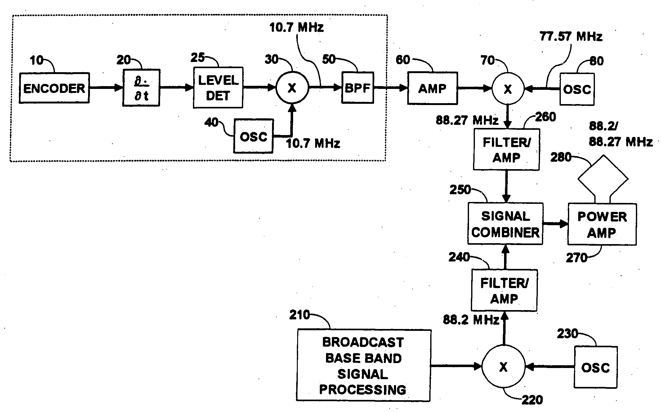
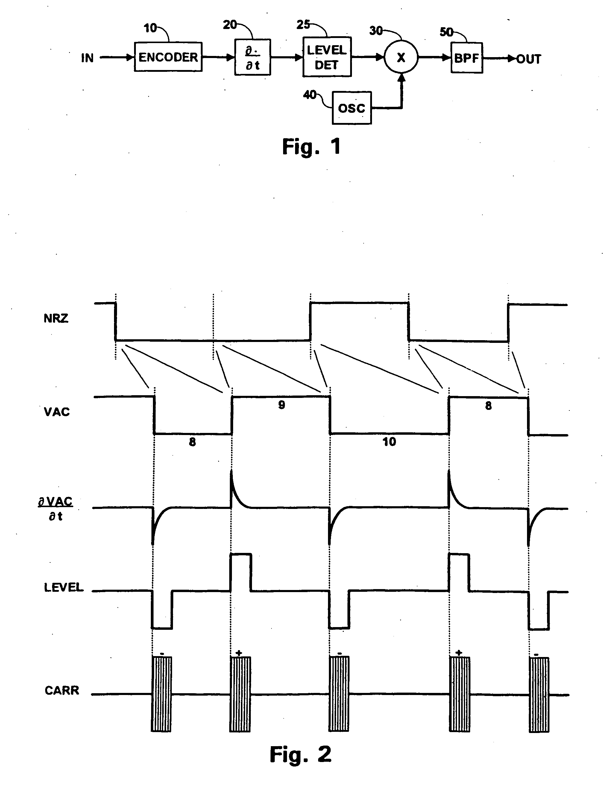
FIG. 1 is a block diagram of a modulator which may be used in the present invention. In FIG. 1, an input terminal IN receives a digital signal. The input terminal IN is coupled to an input terminal of an encoder 10. An output terminal of the encoder 10 is coupled to an input terminal of a differentiator 20. An output terminal of the differentiator 20 is coupled to an input terminal of a level detector 25. An output terminal of the level detector 25 is coupled to a first input terminal of a mixer 30. A local oscillator 40 is coupled to a second input terminal of-the mixer 30. An output terminal of the mixer 30 is coupled to an input terminal of a bandpass filter (BPF) 50. An output terminal of the BPF 50 is coupled to an output terminal OUT, which generates a modulated signal representing the digital signal at the input terminal IN.

FIG. 2 is a waveform diagram useful in understanding the operation of the modulator illustrated in FIG. 1. FIG. 2 is not drawn to scale in order to more c...


PUM


Abstract

An FM broadcast transmitter transmits a broadcast signal having a carrier at a broadcast frequency and sidebands, able to be transmitted at full power, within a transmission band-width around the carrier. It includes a source of a modulated FM stereo signal having a carrier at the broadcast frequency and having sidebands with a bandwidth less than the transmission bandwidth representing a stereo signal. It also includes a source of a modulated IBOC signal, having carrier pulses spaced relative to each other to represent the IBOC digital data signal encoded as a variable pulse width encoded signal, and a bandwidth within the transmission bandwidth not overlapping the FM stereo signal sidebands. A signal combiner combines the modulated FM stereo signal and the modulated IBOC signal to form the broadcast signal. An FM broadcast receiver receives a broadcast signal including a first modulated signal representing an FM stereo signal, and a second modulated signal, having carrier pulses spaced relative to each other to represent an in-band-on-channel (IBOC) digital data signal encoded as a variable pulse width encoded signal. It includes a signal separator for generating a first separated signal representing the FM stereo signal and a second separated signal representing the IBOC digital data signal. An FM signal processor generates a stereo audio signal represented by the FM stereo signal. An IBOC signal processor generates a digital data signal represented by the IBOC digital data signal.

Description

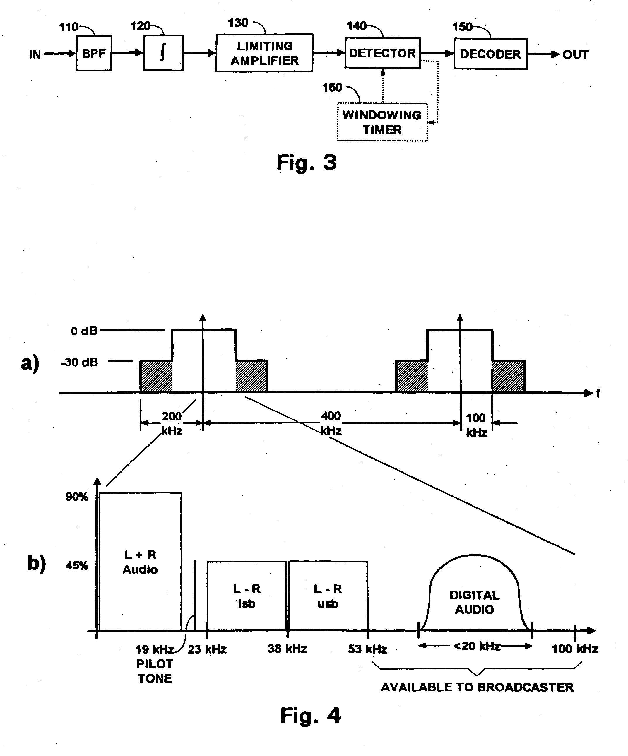
FIELD OF THE INVENTION The present invention relates to a modulation technique which provides a high data rate through band limited channels, and in particular to an in-band-on-channel (IBOC) FM broadcast modulation system for digital data, especially digital audio. BACKGROUND OF THE INVENTION In the United States, FM broadcasters can transmit information in sidebands within 100 kHz of their assigned carrier frequency at full power, and from 100 kHz to 200 kHz around the carrier at 30 dB down from full power. The standard stereo audio signal is placed in a bandwidth within 53 kHz of the carrier. The broadcaster is, thus, able to transmit other information in the remainder of the bandwidth, subject to the constraints described above. It has become desirable for FM broadcasters to simultaneously broadcast stereo audio and digital data. The digital data could, for example, represent a high quality version of the stereo audio being broadcast. This requires a relatively high data rate...

Claims


Application Information

Patent Timeline
IPC IPC(8): H04B1/04H04B1/16H04H20/30
CPCH04H2201/183H04H20/30H04H20/47
Inventor MOHAN, CHANDRAZHANG, ZHIMINGAPRAEZ, MANUEL
Owner THOMSON LICENSING SA
Why Eureka
Try Eureka