Method and device for manufacturing bellows tube

a manufacturing method and bellows tube technology, applied in the field of manufacturing bellows tubes, can solve the problems of increasing idle time every time the mold block train is assembled, deterioration of resin remaining in the barrel of the extruder and the extrusion die, and requiring troublesome work in the composition of the new mold block trains. to achieve the effect of efficient manufacturing of bellows tubes

Inactive Publication Date: 2005-01-20
SANOH KOGYO KK
View PDF8 Cites 11 Cited by
  • Summary
  • Abstract
  • Description
  • Claims
  • Application Information

AI Technical Summary

Benefits of technology

[0010] Accordingly, it is an object of the present invention to solve the foregoing problems in the prior art, and to provide a method of manufacturing a bellows tube, capable of changing old mold block trains for new mold block trains without requiring preparatory work when the quality of the bellows tube is changed, and of efficiently manufacturing bellows tubes of different qualities by optionally changing the arrangement of the elemental mold blocks of the mold block trains according to the patterns of bellows tubes, and an apparatus for carrying out the method.

Problems solved by technology

Composition of the new mold block trains requires troublesome work for removing the elemental mold blocks forming the old mold block trains, and arranging the elemental mold blocks to form the new mold block trains.
Since the extruder is stopped for a time necessary to compose the new mold block trains, idle time increases every time the mold block trains are changed.
Moreover, the resin remaining in the barrel of the extruder and the extrusion die often deteriorates while the extruder is stopped.
Such a mode of work not only causes loss of the resin, but also needs much time and is an impediment to the improvement of productivity.

Method used


Image

  • Method and device for manufacturing bellows tube
  • Method and device for manufacturing bellows tube
  • Method and device for manufacturing bellows tube

Examples


Embodiment Construction

[0024] A bellows tube manufacturing method and a bellows tube manufacturing system embodying the present invention will be described with reference to the accompanying drawings.

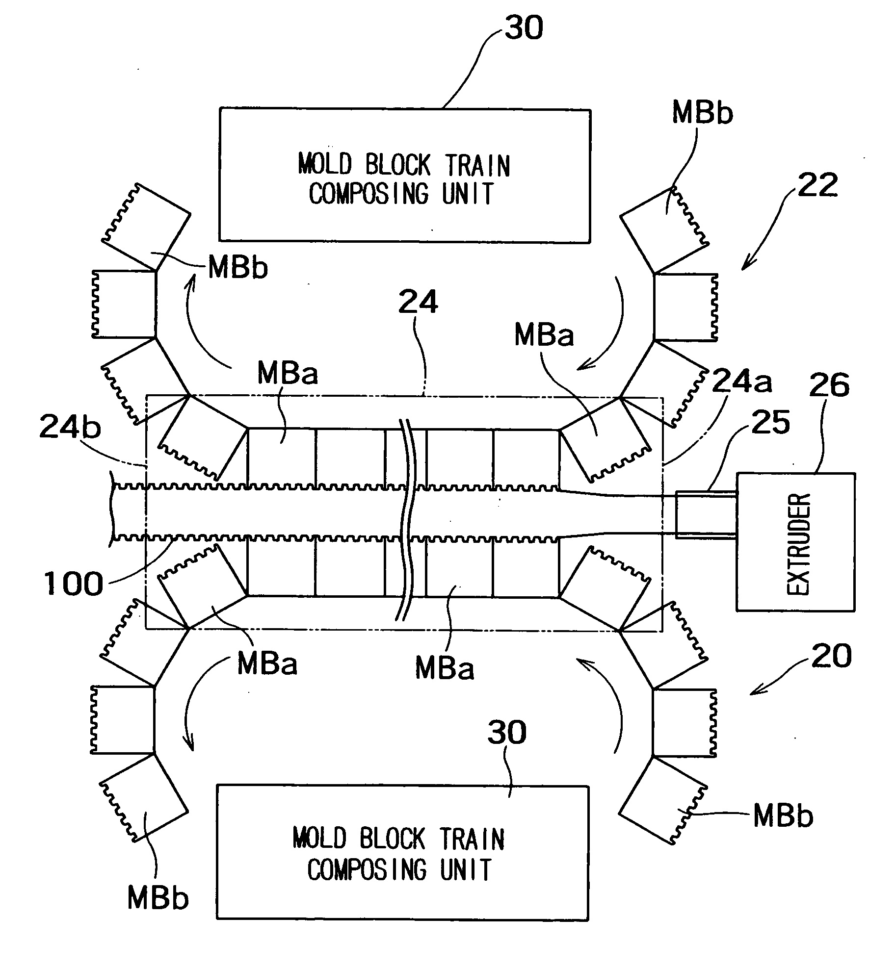
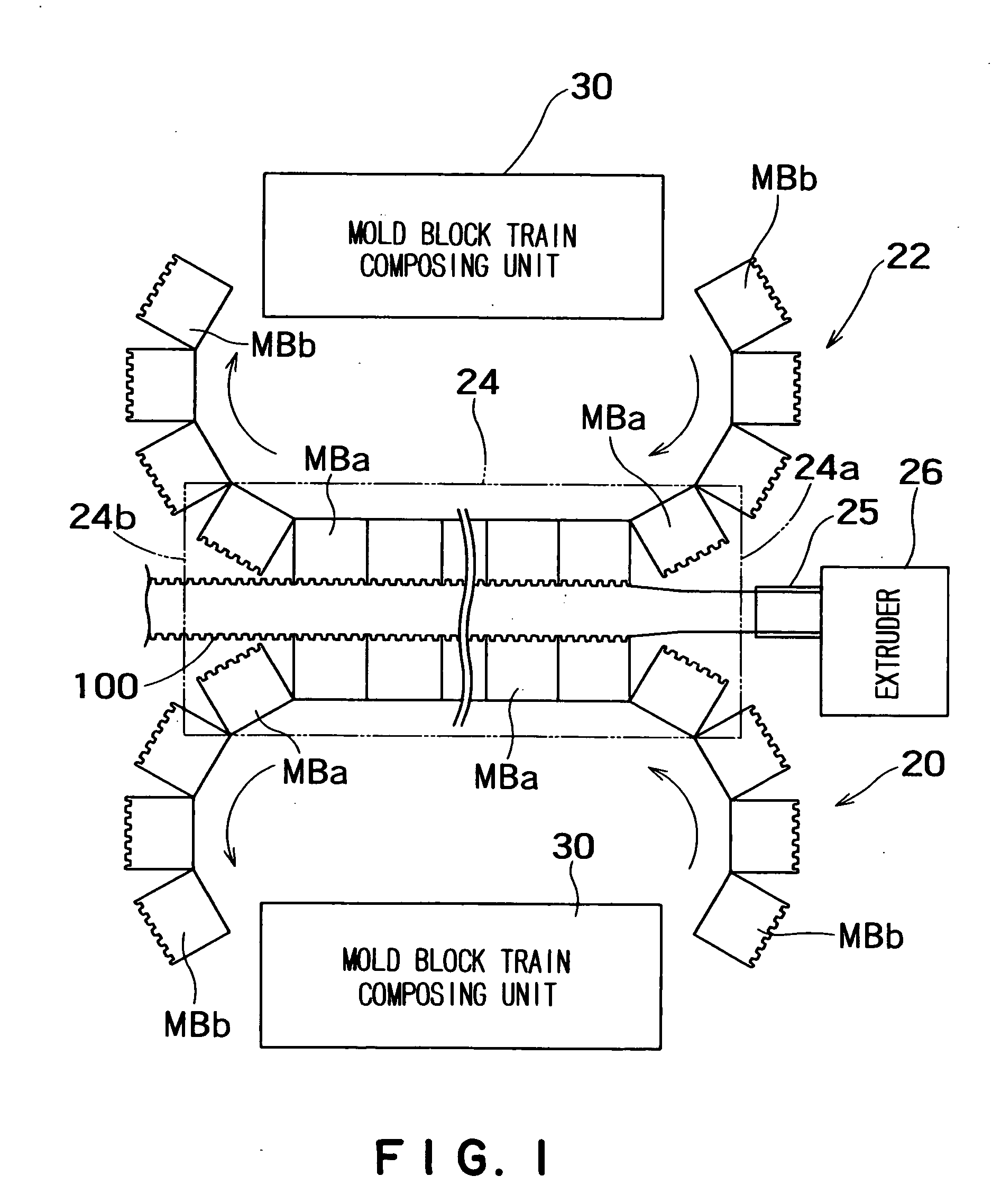
[0025]FIG. 1 is a typical view of a molding unit included in a bellows tube manufacturing system in a first embodiment according to the present invention. In FIG. 1, indicated at 20 is a first mold block train and at 22 is a second mold block train.

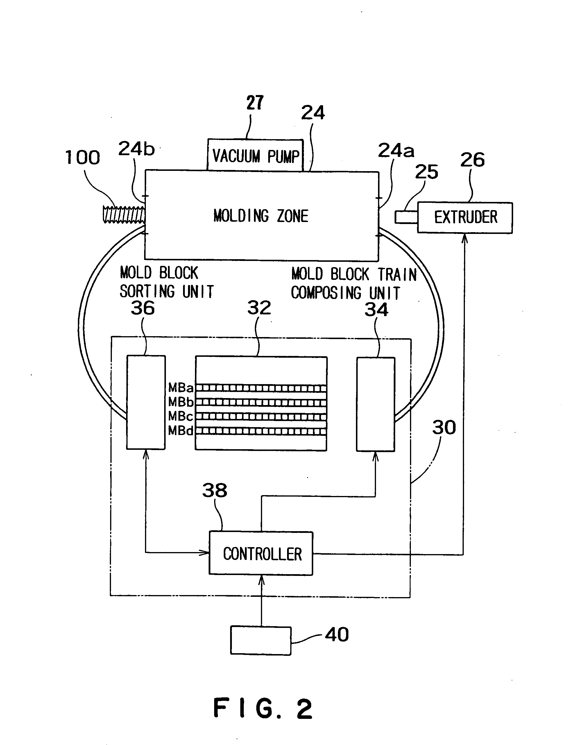
[0026]FIG. 2 is a block diagram of a first mold block train composing unit 30 for composing the first mold block train 20. A second mold block train composing unit for composing the second mold block train is the same as the mold block train composing unit 30 and hence the illustration of the second mold block train composing unit in FIG. 2 is omitted.

[0027] Each of the first mold block train 20 and the second mold block train 22 is formed by arranging half elemental mold blocks MB capable of forming the shape elements shown in FIG. 6 in a row. The elemental mol...


PUM

PropertyMeasurementUnit
shapesaaaaaaaaaa
pressureaaaaaaaaaa
compositionaaaaaaaaaa

Abstract

A bellows tube manufacturing method and a system for manufacturing bellows tubes enables composing new mold block trains for molding a bellows tube of a new pattern and sending the new mold block trains into a molding zone without requiring any preparatory operation and without stopping the bellows tube manufacturing system, and manufacturing bellows tubes at high productivity. Elemental mold blocks MBa, MBb, MBc and MBd necessary for composing a first mold block train 20 and a second mold block train 22 for forming elemental molds having molding surfaces conforming to the shape of a bellows tube to be manufactured are selected and arranged according to composition data specifying the numbers, types and order of arrangement of the elemental mold blocks MBa, MBb, MBc and MBd to compose the first mold block train 20 and the second mold block train 22, and the mold block trains 20 and 22 are moved into a molding zone 24. A molten resin is extruded into a space between the mold block trains 20 and 22 moving in the molding zone 24 through an extrusion die 25 by an extruder 26. The corresponding elemental mold blocks MB of the mold block trains 20 and 22 are clamped to form the elemental molds having cavities as the mold block trains 20 and 22 move in the same direction, and a negative pressure is produced in the cavities to mold a bellows tube. The elemental mold blocks MB of the mold block trains 20 and 22 returned from the molding zone 24 are sorted according to type.

Description

DESCRIPTION TECHNICAL FIELD [0001] The present invention relates to a method of manufacturing a bellows tube made of a resin for use in fuel supply piping, hydraulic piping and pneumatic piping on an automobile or such, and a bellows tube manufacturing system for carrying out the method. BACKGROUND ART [0002]FIG. 5 shows a resin bellows tube 2 made of a resin. Since the resin bellows tube 2 has high strength and high corrosion resistance and is flexible, the resin bellows 2 is used often in a fuel supply piping to be installed in a narrow space in an automotive body. Usually, the bellows tube 2 has a pleated tubular body 3, a straight tubular part 4 to be connected to a union joint, formed integrally with the pleated tubular body 3. The pleated tubular part 3 needs to be held fixedly with a clip or the like when the arrangement of pipes requires. Therefore, some bellows tube is provided with a straight tubular part 4 in its middle part. [0003]FIG. 6(a) to 6(d) show representative sh...

Claims


Application Information

Patent Timeline
Patent Type & Authority Applications(United States)
IPC IPC(8): B29C48/32B29C33/30B29C48/09B29C48/30B29C48/90B29C48/92B29C49/00B29C49/04B29C49/78B29L23/18
CPCB29C33/308B29C47/92B29C47/0033B29C47/0038B29C47/126B29C49/0021B29C49/04B29C49/78B29C2791/001B29C2791/006B29C2791/007B29C2947/9258B29C2947/92609B29C2947/92933B29K2021/00B29L2016/00B29L2023/18B29L2023/183B29C47/0023B29C48/92B29C48/09B29C48/13B29C48/001B29C48/303B29C2948/9258B29C2948/92609B29C2948/92933B29C49/0025B29C49/0027
Inventor KIMURA, HIDEKI
Owner SANOH KOGYO KK
Why Eureka
Try Eureka