Liquid-discharging apparatus

a technology of liquid storage and liquid storage, which is applied in the direction of printing, other printing apparatus, etc., can solve the problems of inapplicability of techniques, inability to discharge ink, and small amount of discharged ink, so as to prevent the quality of dot arrays or dots, and easily view the displayed work volumes

Inactive Publication Date: 2005-01-20
SONY CORP
View PDF1 Cites 32 Cited by
  • Summary
  • Abstract
  • Description
  • Claims
  • Application Information

AI Technical Summary

Benefits of technology

[0013] Therefore, in the liquid-discharging head with a head cap having a cleaning member and a waste-liquid receiver, it is possible to properly determine the timing of replacement of the head cap during use.
[0014] Preferably, the liquid-discharging apparatus further includes a control unit that receives the work volumes from two accumulated-volume storage unit, and stops a subsequent liquid-discharging operation when one of the work volumes exceeds a predetermined upper limit. Accordingly, it is possible to automatically stop the liquid-discharging operation, and prevent the quality of dot arrays or dots formed by the liquid-discharging nozzles from being reduced by the excess of the work volume over the predetermined upper limit.
[0015] Preferably, an output signal from the information output unit is sent to a display unit for displaying the driving states of units provided in a main assembly of the apparatus. This allows the user to view the content concerning the work volumes displayed on the display unit, and to properly determine the timing of replacement of the head cap.
[0016] Preferably, an output signal from the information output unit is sent to a display unit for displaying the content of information processing of an information processing apparatus connected to a main assembly of the apparatus. This allows the user to view the content concerning the work volumes displayed on the display unit of the information processing apparatus, and to properly determine the timing of replacement of the head cap.
[0017] Preferably, the output signal from the information output unit includes a signal for displaying the work volumes from the accumulated-volume storage unit in the form of a numeral, a graph, or an image. In this case, the user can easily view the displayed work volumes.

Problems solved by technology

Even when idle discharging into the waste-ink receiver is performed, the amount of discharged ink is small and the ink naturally dries because the print head has a small number of nozzles.
However, this technique is not applicable to a print head which also includes a cleaning member that wipes (absorbs) ink while moving on the nozzle surface, and in which the amount of ink absorbed by the cleaning member is detected, and the timing of replacement of the cleaning member is determined by the accumulated amount of absorbed ink.
Therefore, in a print head having both a waste-ink receiver and a cleaning member, it is sometimes impossible to properly determine the timings of replacement of the discharged-receiver and the cleaning member during the use.

Method used


Image

  • Liquid-discharging apparatus
  • Liquid-discharging apparatus
  • Liquid-discharging apparatus

Examples


Embodiment Construction

[0030] An embodiment of the present invention will be described in detail below with reference to the attached drawings.

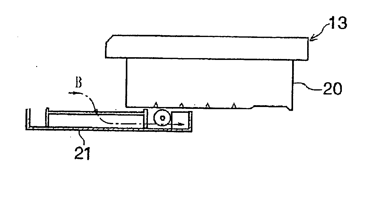
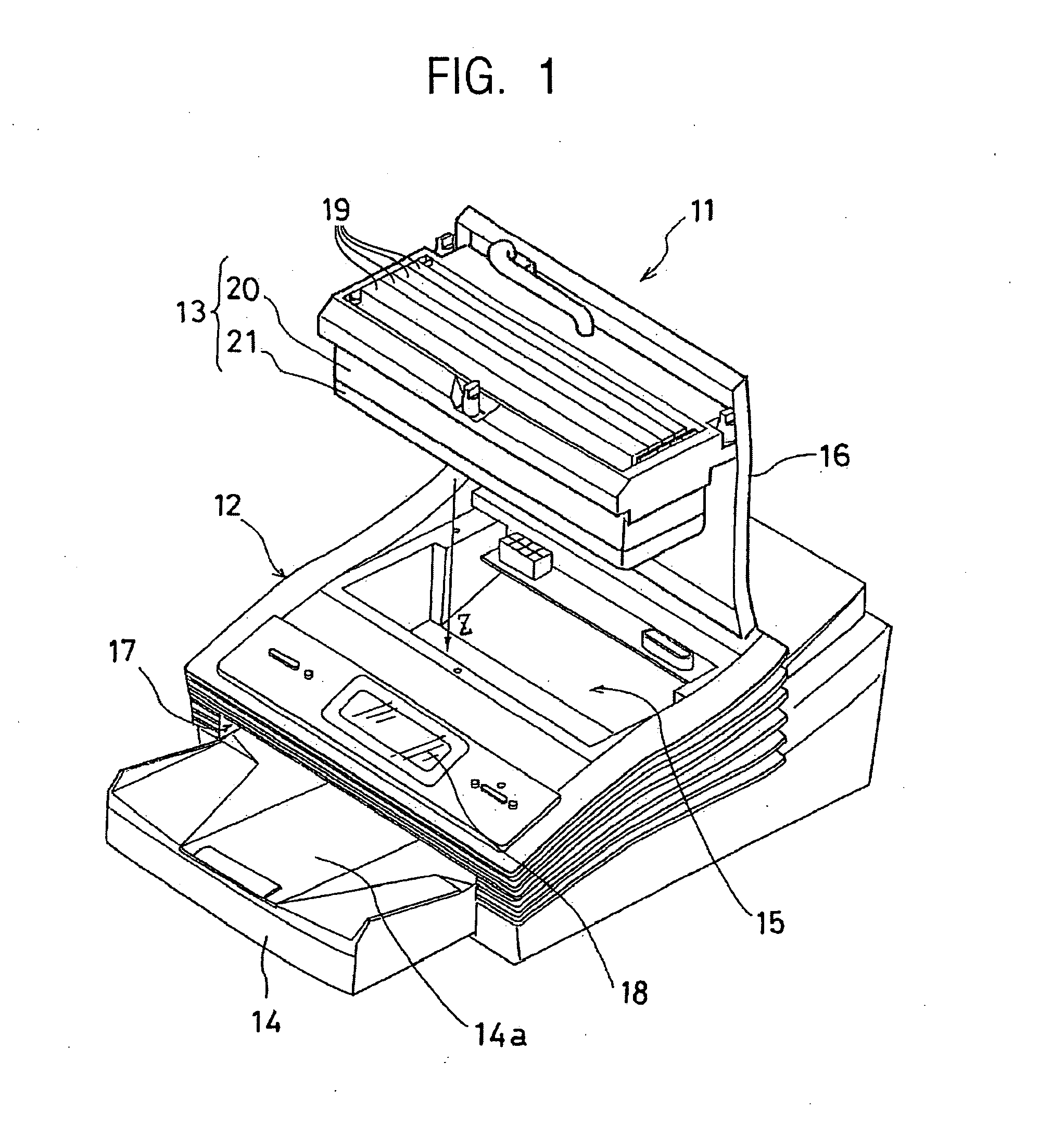
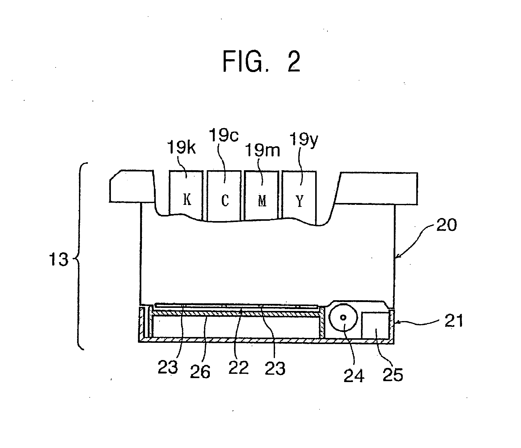
[0031]FIG. 1 is a perspective view of an ink-jet printer serving as a liquid-discharging apparatus according to an embodiment of the present invention. An ink-jet printer 11 forms an image by discharging ink droplets onto required positions on a recording medium, and includes a main assembly 12, a head cartridge 13, and a recording-sheet tray 14.

[0032] A recording-sheet feeding mechanism and an electric circuit section for performing proper printing on a recording sheet serving as a recording medium are provided inside the main assembly 12. A storage section 15 for accommodating the head cartridge 13 is open at the top of the main assembly 12, and an upper cover 16 is provided at the top end of the storage section 15 to open and close the storage section 15. A tray insertion slot 17 in which a recording-sheet tray 14, which will be described later, is mounted is ...


PUM


Abstract

In a liquid-discharging apparatus, the work volume of a cleaning roller of a liquid-discharging head and the work volume of a waste-liquid receiver of a head cap are displayed. A dot array or a dot is formed by discharging a predetermined liquid from a plurality of liquid-discharging nozzles provided on a nozzle surface of the liquid-discharging head. The liquid-discharging apparatus includes a roller-wiping-count storage unit for storing the accumulated work volume of the cleaning roller during a period from the beginning of use to the present time, an idle-discharging-count storage unit for storing the accumulated work volume of the waste-liquid receiver during the period, and an information output unit that receives the work volumes from the storage units, and that outputs both of or the higher one of the work volumes.

Description

BACKGROUND OF THE INVENTION [0001] 1. Field of the Invention [0002] The present invention relates to a liquid-discharging apparatus that forms dot arrays or dots by discharging a predetermined liquid from liquid-discharging nozzles provided in a liquid-discharging head. [0003] 2. Description of the Related Art [0004] In known serial-head ink-jet printers, a print head having a size shorter than the print width of recording paper performs printing while moving from side to side. In this case, in order to prevent printing failure due to clogging of ink-discharging nozzles, idle discharging of ink is performed in a state in which the print head is positioned at a waste-ink receiver provided outwardly separate from the recording paper, and nozzle cleaning is performed by absorbing ink in a state in which the print head is positioned at an ink-absorbing mechanism provided in a head cap outwardly separate from the recording paper. [0005] It is relatively easy to do nozzle cleaning in the ...

Claims


Application Information

Patent Timeline
Patent Type & Authority Applications(United States)
IPC IPC(8): B41J2/175B41J2/165B41J2/17B41J2/185
CPCB41J2/16523B41J2002/1742B41J2/1721B41J2/16585B41J2/16517B41J2/16535B41J29/393B41J2002/16573
Inventor ISHIHARA, MITSUGU
Owner SONY CORP
Why Eureka
Try Eureka