Means for controlling a coil arrangement with electrically variable inductance

Inactive Publication Date: 2005-01-20
MINEBEA CO LTD
View PDF9 Cites 6 Cited by
  • Summary
  • Abstract
  • Description
  • Claims
  • Application Information

AI Technical Summary

Benefits of technology

[0021] The technician will recognize that lower values for Rs slow down the turn-on process, that is the change in inductance from the maximum value to the minimum value. With regard to high efficiency, Rs should, on the other hand, be small. Thus to accelerate the turn-on process, either Rp can be reduced or Vc increased. The first mentioned strategy is effective as soon as Rp is less than n2 Rs. The most effective means of accelerating the turn-on speed, however, is by increasing Vc.
[0022] During turn-off, the switch S normally remains open (or high ohmic). The magnetic field decreases with the same speed as the current through n2Rs decreases: iL=iL(0·ⅇn2·RsLc·t⁢…⁢ⅆiLⅆt=-iL⁡(0)·n2·RsLc·ⅇn2·RsLc·t(3)
[0023] The technician will be aware that the speed or rate of change is small because Rs has to be kept small when efficiency is taken into consideration.
[0024] Equation (2) opens up another p

Problems solved by technology

The duration and absolute value of the inverse voltage pulse is, however, critical inasmuch as an pulse that is too sho

Method used


Image

  • Means for controlling a coil arrangement with electrically variable inductance
  • Means for controlling a coil arrangement with electrically variable inductance
  • Means for controlling a coil arrangement with electrically variable inductance

Examples


Embodiment Construction

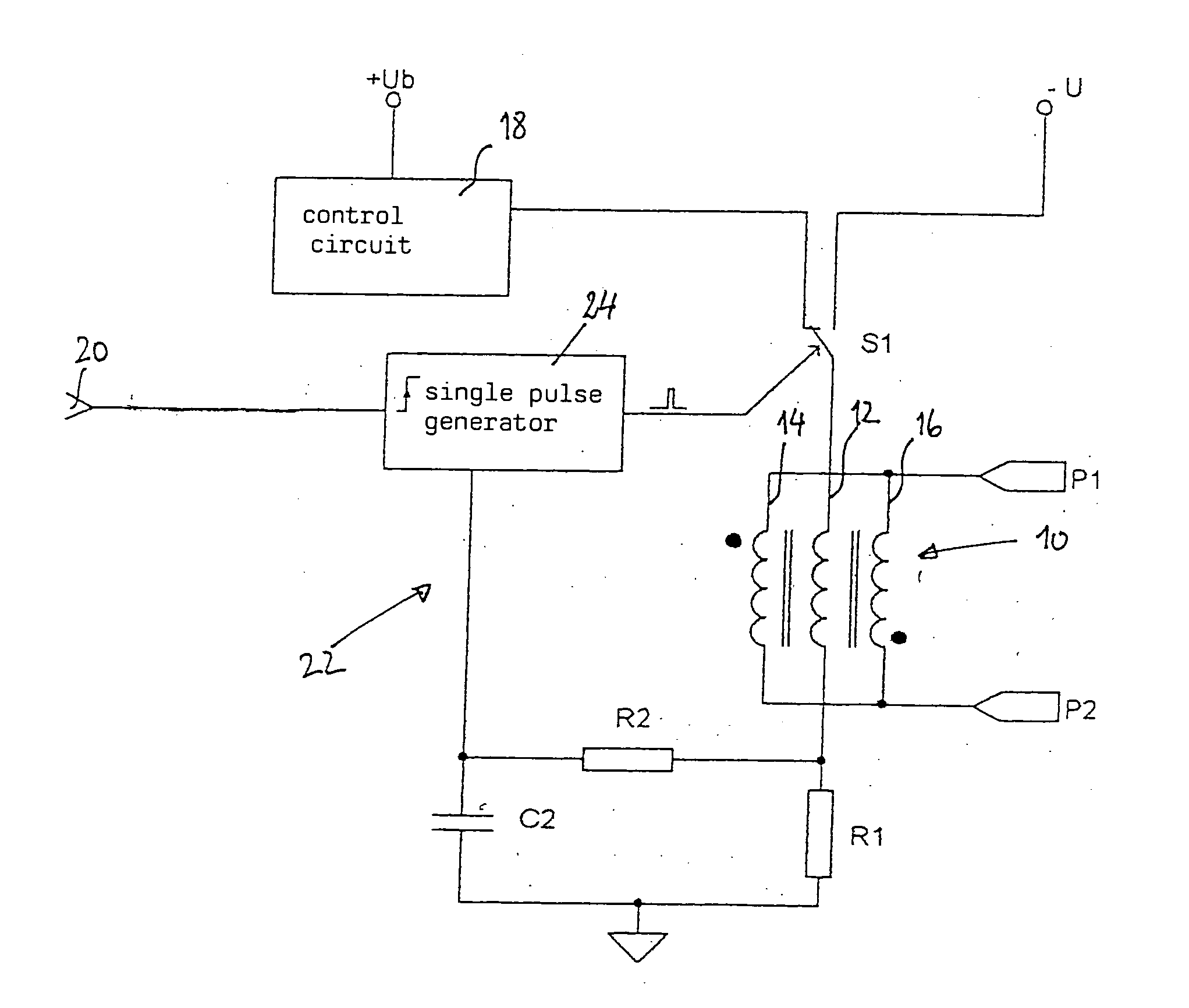
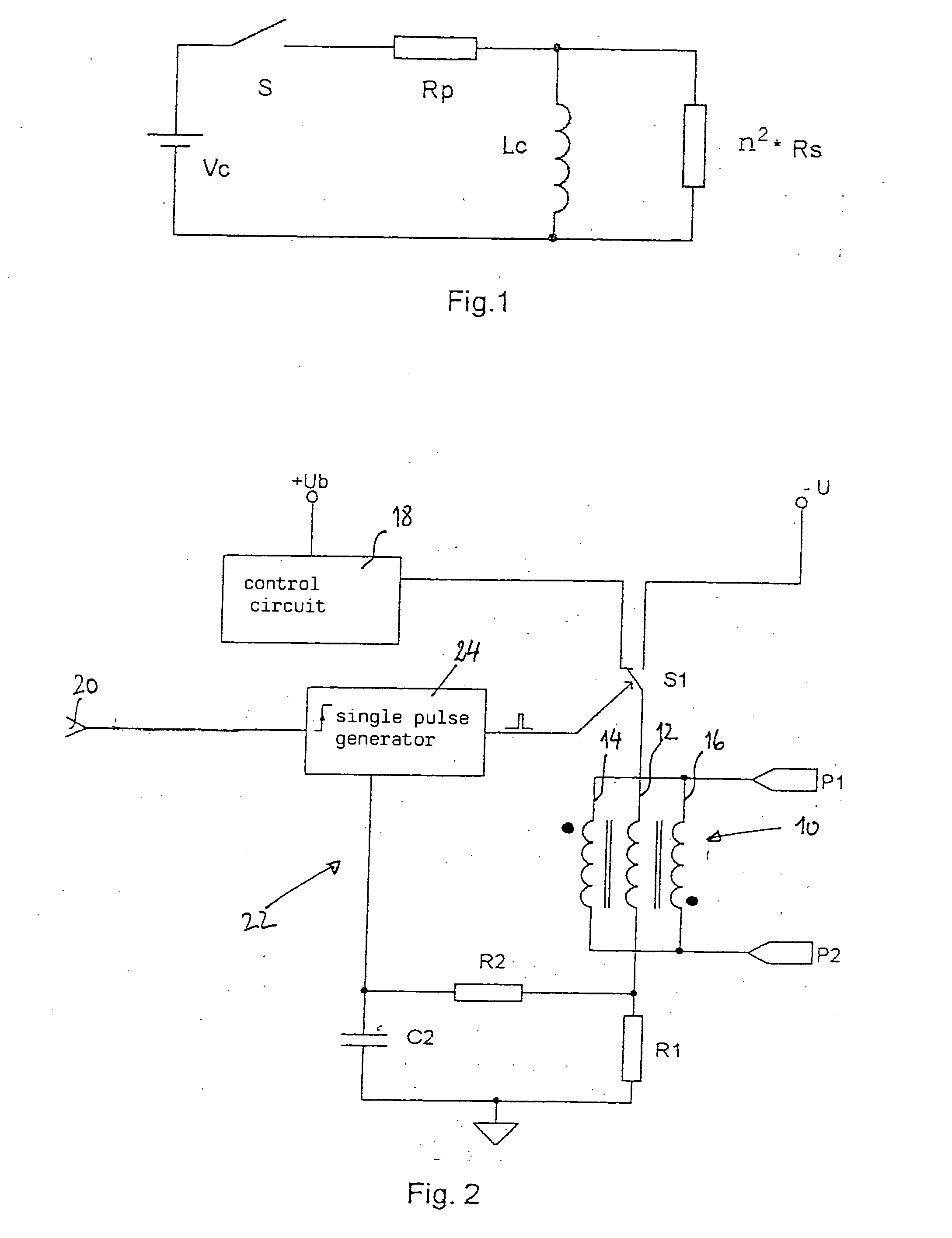
[0031]FIG. 2 shows an example of a circuit to control a coil arrangement with variable inductance in accordance with the invention. The coil arrangement in general is indicated by 10 in FIG. 2 and comprises a control winding 12 and two working windings 14, 16 connected in parallel. During normal operation, the coil arrangement 10 is controlled using a conventional control circuit 18. The control circuit 18 is connected to the coil arrangement 10 via a switch S1. In practice, the coil arrangement 10, for example, can be integrated together with the control circuit 18 in the secondary regulation loop of a switching power supply.

[0032] When the circuit in FIG. 2 receives a signal at an input 20 that calls for a rapid turn-off of inductance, (i.e. a rapid increase of inductance), a demagnetization circuit is activated which is indicated in general by 22 in FIG. 2. Rapid turn-off of the variable inductance could be necessary, for example, if the threat of a strong voltage overshoot duri...


PUM


Abstract

The invention relates to a special control for current-controlled inductors which allows inductance to be varied at a considerably faster rate than is the case in the prior art. The control presented in the invention can be employed for coil arrangements which carry at least one control winding and at least two working windings on a ferro or ferromagnetic core material. The accelerated change in inductance is achieved by means of a demagnetizing inverse voltage impulse which is generated by a special part of the circuit.

Description

FIELD OF THE INVENTION [0001] The invention relates to a means for controlling a coil arrangement with electrically variable inductance and a coil device comprising such a coil arrangement with variable inductance which can be controlled by means of a current. BACKGROUND OF THE INVENTION [0002] The invention especially relates to a means for controlling a coil arrangement with variable inductance which allows the inductance to be varied at particularly rapid rates. This means can then be used whenever the inductance of the coil arrangement is varied by means of current-induced pre-magnetization and when at least two working windings are provided which are connected in parallel. [0003] The invention can basically be employed in all applications in which current-controlled, variable inductors are needed to control an electric alternating current. More specifically, the invention can be applied to current-controlled, variable inductors having a control winding and two working windings ...

Claims


Application Information

Patent Timeline
IPC IPC(8): H01F27/38H01F27/42H01F29/14
CPCH01F27/38H01F29/14H01F27/42
Inventor WEGER, ROBERT
Owner MINEBEA CO LTD
Why Eureka
Try Eureka