
Energy Dissipative Device and Method

a technology of energy dissipation device and energy, which is applied in the direction of electric apparatus casing/cabinet/drawer, instruments, machine supports, etc., can solve problems such as energy dissipation, and achieve the effect of improving protection from shock and vibration

Active Publication Date: 2005-01-20
OLIXIR TECH CORP
View PDF26 Cites 19 Cited by
  • Summary
  • Abstract
  • Description
  • Claims
  • Application Information

AI Technical Summary

Benefits of technology

[0045] Against the described background, it is therefore a general object of the invention to provide improved protection from shock and vibration for electronic devices, especially disk drives and other data storage devices, which may by portable or fixed.
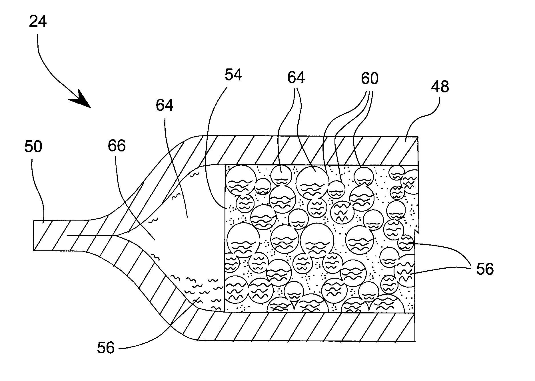
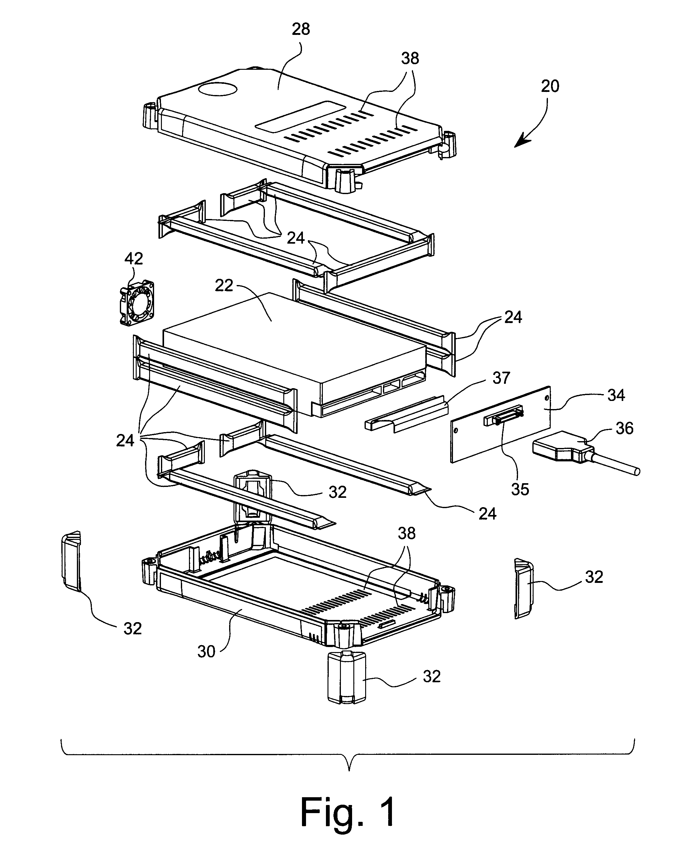
[0050] According to another aspect of the invention, a host module assembly protects a hosted device from shock and vibration. The assembly includes a case, housing, or container suitably configured to receive a hosted device therein and to receive at least one mechanical energy dissipative element between the hosted device and the case. A hosted device is located within the case. Also, at least one mechanical energy dissipative element is located between the hosted device and the case. The mechanical energy dissipative element is formed of a closed envelope having an elastic, resilient wall that defines an enclosed internal volume. A porous body of elastic material is contained within the internal volume of the closed envelope. The porous body defines a network of cells interconnected through cell orifices suitably configured for passing viscous liquid between cells. A viscous liquid is contained within the envelope, filling at least a portion of the network of interconnected cells. Under compression or expansion of the porous body, the viscous liquid flows through the cell orifices and thereby dissipates energy resulting from an external force applied against the elastic wall. A compressible gas also occupies a portion of the internal volume of the envelope.
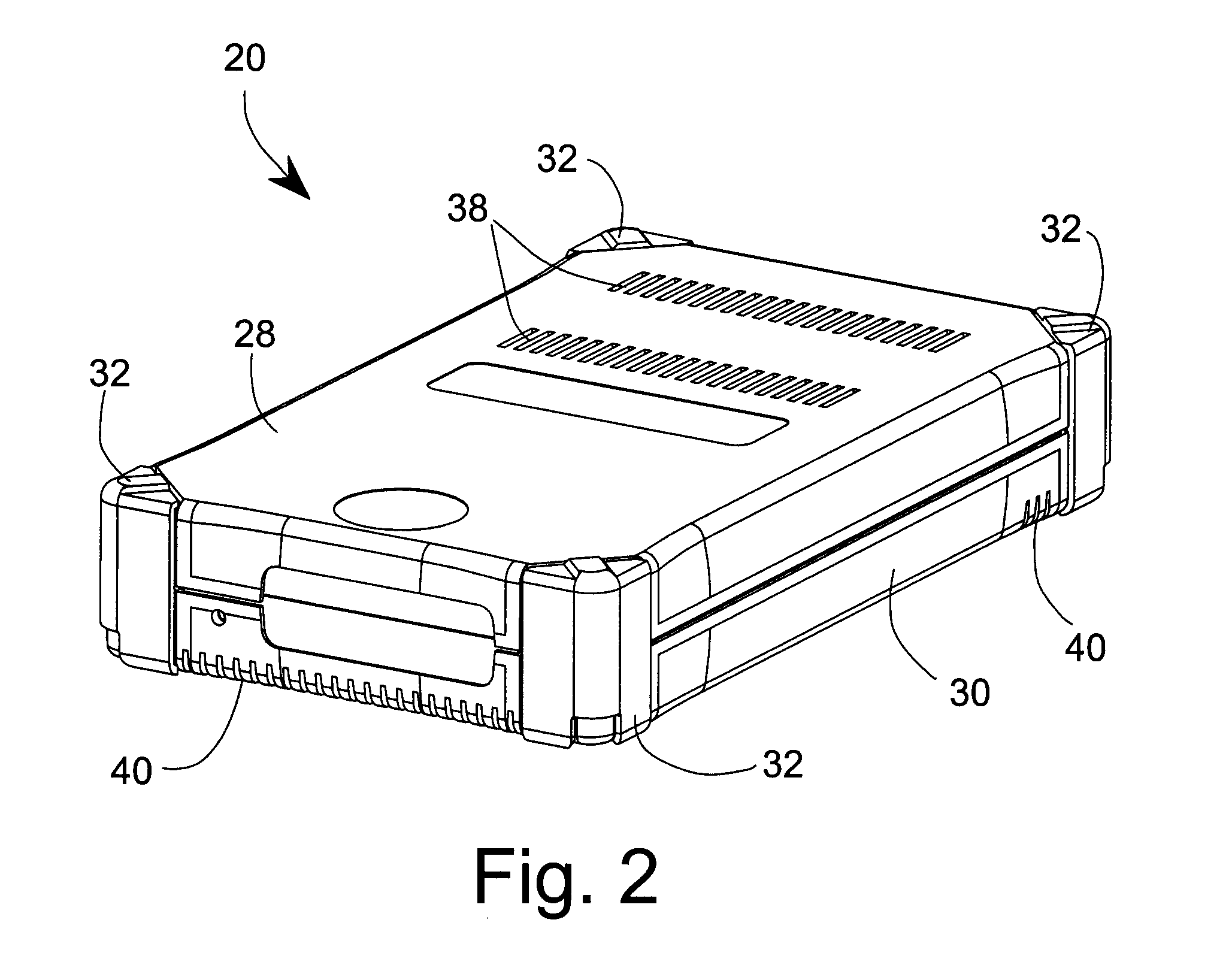
[0053] In a specifically desirable version of the invention, the hosted device is a disk drive and the case is a common form factor envelope. The resulting structure provides a ruggedized disk drive module. The disk drive can be selected from 3.5-inch, 3.0-inch, 2.5-inch, or 1.0-inch form factor disk drives. The case can be adapted for mounting into a computer system, with the result that the mechanical energy dissipative element provides the protection from shock and vibration during the installation of the disk drive module into a computer system. Either a single disk drive cartridge or a plurality can be mounted into a computer system. The mechanical energy dissipative element is functional to protect against shock and vibration during the installation of a plurality of the disk drive modules into a dense array of disk drives in a computer system. The case also may be a container used in handling a disk drive during manufacture or installation, protecting the disk drive from shock and vibration during handling.

Problems solved by technology

As a result, under compression or expansion of the porous body, the viscous liquid flows through the cell orifices and thereby dissipates energy resulting from an external force applied against the elastic wall.

Method used


Image

  • Energy Dissipative Device and Method
  • Energy Dissipative Device and Method
  • Energy Dissipative Device and Method

Examples


example 1

[0097] The portable module 20 uses thirteen MEDEs. The materials and their respective dimensions are as follows:

[0098] 13 MEDEs Per Module (Finished Lengths Approximate):

[0099] 1. 4 MEDEs @ 13.34 cm (5.250 inch) finished size.

[0100] 2. 1 MEDE @ 8.57 cm (3.375 inch) finished size.

[0101] 3. 4 MEDEs @ 0.59 cm (1.5 inch) finished size.

[0102] 4. 4 MEDEs @ 13.34 cm (5.25 inch) finished size.

[0103] Material Needed:

[0104] 1. Latex tubing, 0.254 mm (0.010 inch) wall thickness, 9.53 mm (0.375 inch) I.D. (Kent Elastomer, Kent, Ohio, USA).

[0105] 2. Open-celled polyurethane foam, Confor CF-45 Blue, 9.53 mm (0.375 inch) wide, 3.175 mm (0.125 in) to 6.35 mm (0.25 in) thick (E-A-R Specialty Composites, Indianapolis, Indiana, USA).

[0106] 3. Viscous Liquidpolydimethylsiloxane (PDMS), viscosity 10,000 Cs, (Aldrich Chemicals, Sigma-Aldrich Corp., St. Louis, Mo., USA).

[0107] 4. Vulcanizing fluid, Rema Tip Top (North American, Inc., Northvale N.J., USA); or cyanoacrylate glue, Devcon Flex Supe...


PUM

PropertyMeasurementUnit
heightaaaaaaaaaa
heightaaaaaaaaaa
densityaaaaaaaaaa

Abstract

An energy dissipative element protects hard disk drives from shocks and vibrations. A closed elastic envelope houses a body of open cell foam, a volume of viscous liquid, and a compressible gas. Under compression or expansion of the foam, viscous liquid flows through cell orifices and thereby dissipates energy resulting from external force applied against the elastic wall. The energy dissipative elements are applied between a disk drive housing and an outer case to create a ruggedized portable disk drive module.

Description

BACKGROUND OF INVENTION [0001] 1. Field of the Invention [0002] The invention generally relates to electrical systems and devices. More specifically, the invention relates to a housing or mounting assembly with diverse electrical components, especially to electronic systems and devices. The invention relates to methods and apparatus for cushioning of a computer peripheral from mechanical shocks and vibrations, especially a memory unit peripheral such as a disk drive. The method and apparatus employ highly viscous fluids that flow readily at ordinary ambient temperatures, operative in a porous elastic structure. [0003] 2. Description of Related Art [0004] including information disclosed under 37 CFR 1.97 and 1.98 The term “disk drives” may refer to any of several types of devices, including but not limited to hard disk dives, floppy disk drives, and optical disk dives such as CD and DVD drives. These disk drives share a common characteristic of having one or more rotating recording m...

Claims


Application Information

Patent Timeline
Patent Type & Authority Applications(United States)
IPC IPC(8): G11B33/08G11B33/12G11B33/14
CPCG11B33/08G11B33/142G11B33/12
Inventor DESAI, SHRIKANTSHAH, PRABODH L.CHEIM, DARYL A.SHAH, DARSHAN P.
Owner OLIXIR TECH CORP
Learn More