Multi-lamp arrangement for optical systems

a multi-lamp arrangement and optical system technology, applied in the field of optical systems, can solve the problems of difficult to produce high-bright images from projectors, without using high-power light sources

Active Publication Date: 2005-01-20
PROJECTIONDESIGN
View PDF16 Cites 16 Cited by
  • Summary
  • Abstract
  • Description
  • Claims
  • Application Information

AI Technical Summary

Benefits of technology

This patent describes an improvement on existing optical systems by adding multiple lamps with their own individual light guides all working together through one main light guide. Each lamp sends its light out to its specific guide which then combines them all back up at the end. This results in better overall performance from the system.

Problems solved by technology

The technical problem addressed in this patent is the need for a multi-lamp system that produces a flux level that is equal to or better than known systems, but with fewer lamps, thus yielding reduced material cost, manufaturing cost and operating costs, reduced power consumption and reduced product temeperature, compared to known systems. The invented system may utilize shorter arc gap lamps than the presently known technology, thus producing a better image performance.

Method used


Image

  • Multi-lamp arrangement for optical systems
  • Multi-lamp arrangement for optical systems
  • Multi-lamp arrangement for optical systems

Examples


Embodiment Construction

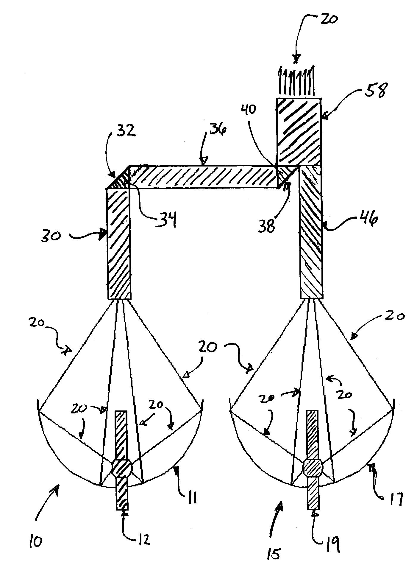
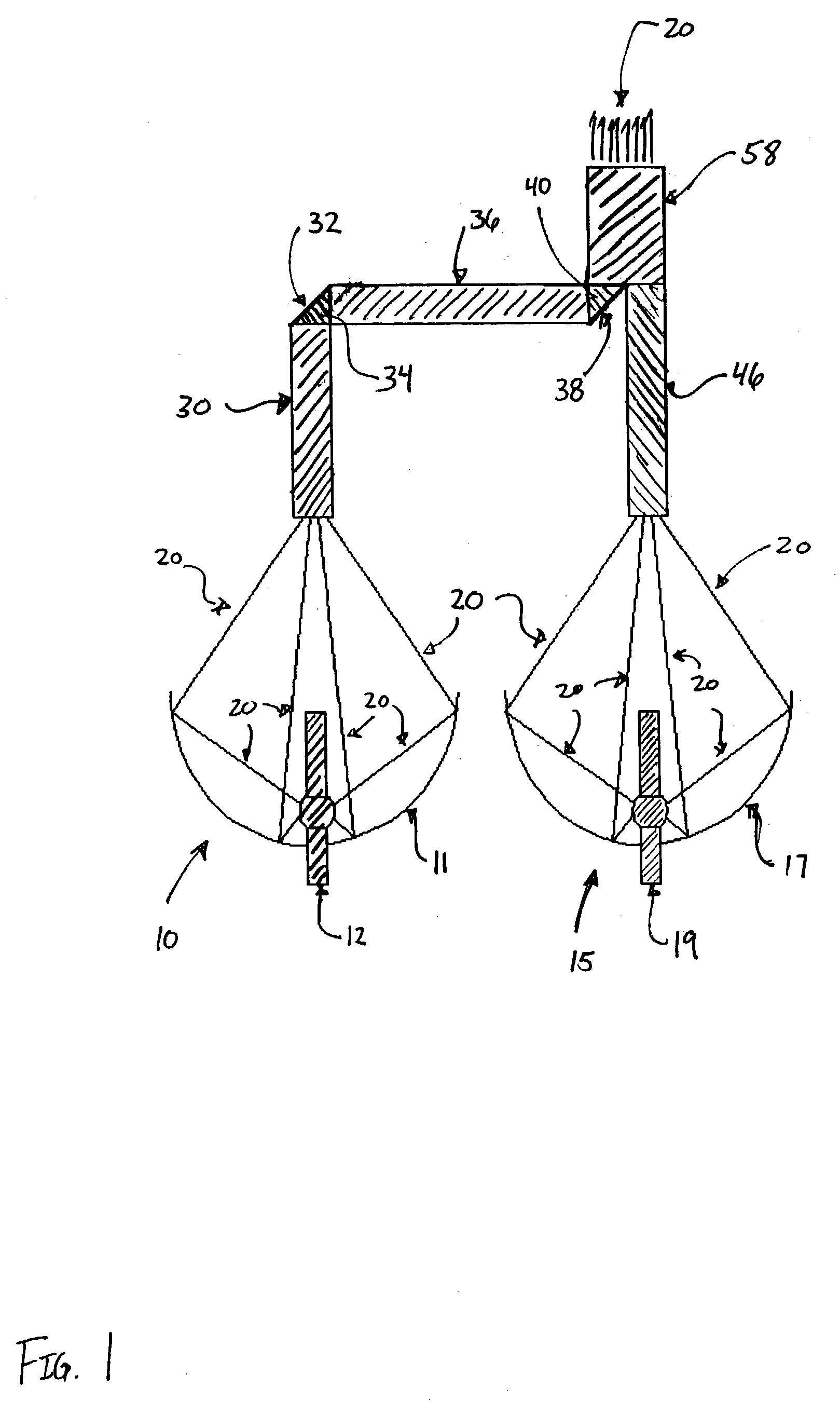
[0017]FIG. 1 is a schematic plan view of an embodiment of the invention, and shows an arrangemnent comprising two lamps 10, 15, each emitting light schematically illustrated by exemplary light beams 20. The person skilled in the art will understand that the system according to the invention may comprise more lamps than two and be arranged in any configuration.

[0018] In general, the multi-lamp arrangement for optical systems according to the invention comprises two or more lamps 10, 15, each lamp positioned such as to transmit light 20 into respective light guides 36, 46 that are both optically connected to a collective light guide 58, out of which the light may be transmitted in any optical system (not shown).

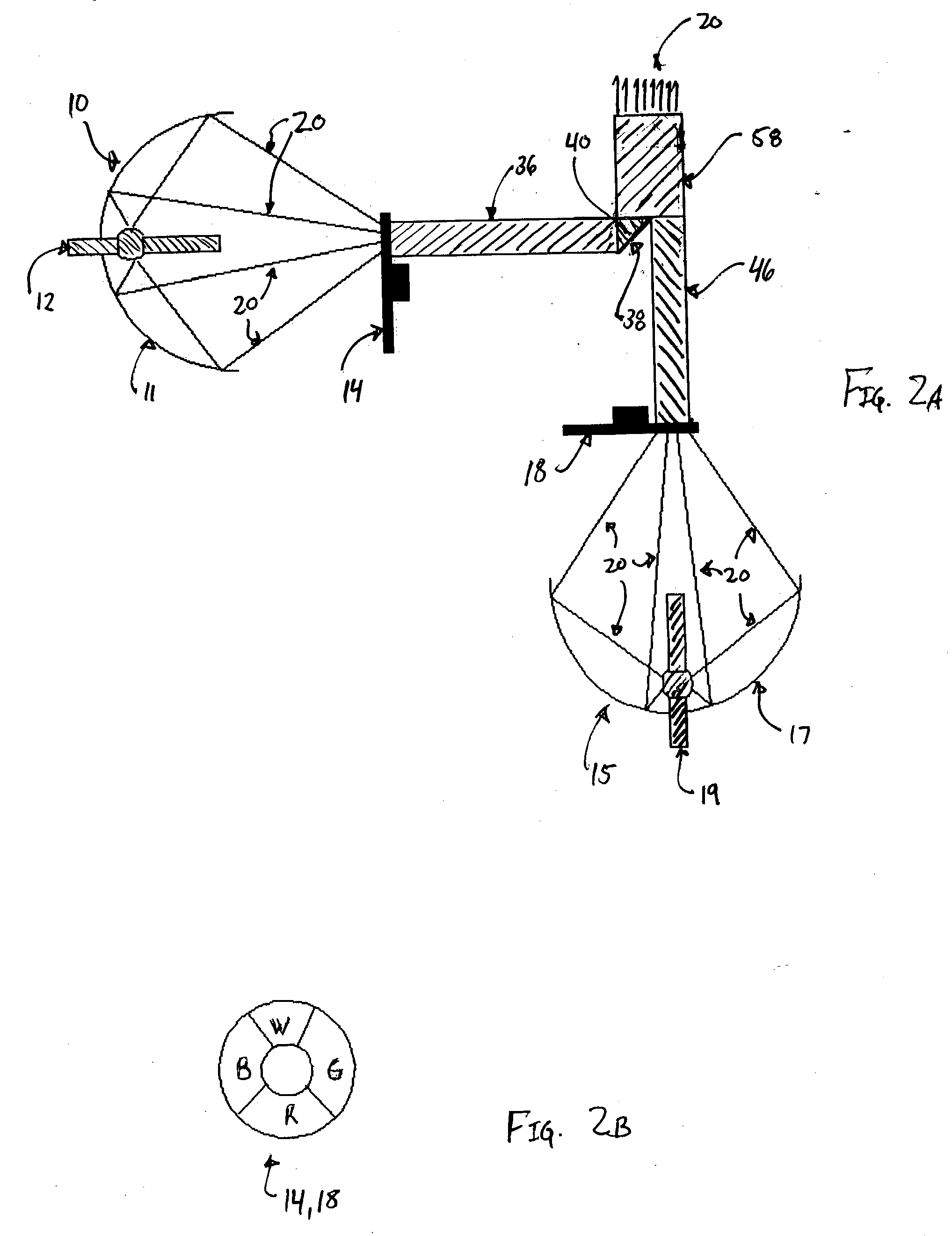
[0019] In one configuration (cf. FIG. 2A), one light guide 36 is optically connected to the collective light guide 58 by means of a mirror 38 and a prism 40. FIG. 2A shows the lamps having individual color modulators 14, 18 positioned between each lamp and their respective li...


PUM


Abstract

A multi-lamp arrangement for optical systems comprising two lamps or more and a collective light guide, where each lamp is positioned such as to transmit light into respective light guides that are both optically connected to the collective light guide. In one embodiment, one of the lamps is optically connected to the collective light guide by means of a mirror (38)-and-prism arrangement and an intermediate light guide and an intermediate mirror (32)-and-prism arrangement. The invention also comprises an augmented color modulator with a number of color fields, where the number of identical color fields are equal to the number of lamps. The multi-lamp system will produce a flux level that is equal to or better than known systems but with fewer lamps, thus yielding reduced material cost, manufacturing cost and operating costs, reduced power consumption and reduced product temperature.

Description


Claims


Application Information

Patent Timeline
Owner PROJECTIONDESIGN
Why Eureka
Try Eureka