Method for prospect identification in asset evaluation

a prospect identification and asset evaluation technology, applied in the field of seismic data interpretation, can solve problems such as taking a year

Inactive Publication Date: 2005-01-20
SCHLUMBERGER TECH CORP
View PDF12 Cites 22 Cited by
  • Summary
  • Abstract
  • Description
  • Claims
  • Application Information

AI Technical Summary

Benefits of technology

[0014] The rapid 3D seismic classification method of the present invention, in conjunction with economics, risk, and decision analyses, can be a powerful tool for oil and gas companies, particularly when informe

Problems solved by technology

Very often, utilizing prior art seismic interpretation methods, it may take a year for a new player to define t

Method used


Image

  • Method for prospect identification in asset evaluation
  • Method for prospect identification in asset evaluation
  • Method for prospect identification in asset evaluation

Examples


Embodiment Construction

[0025] Refer now to the drawings wherein depicted elements are not necessarily shown to scale and wherein like or similar elements are designated by the same reference numeral through the several views.

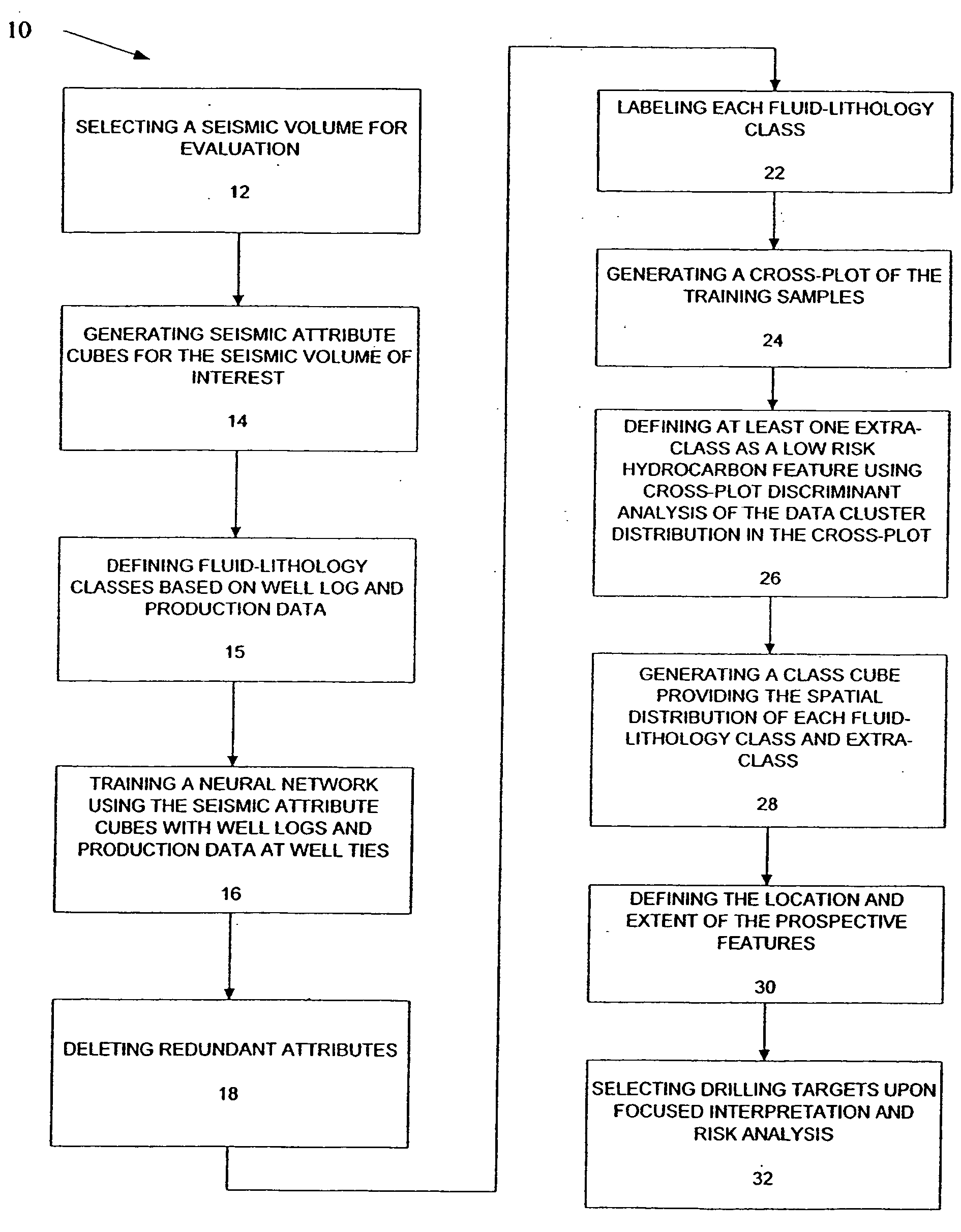
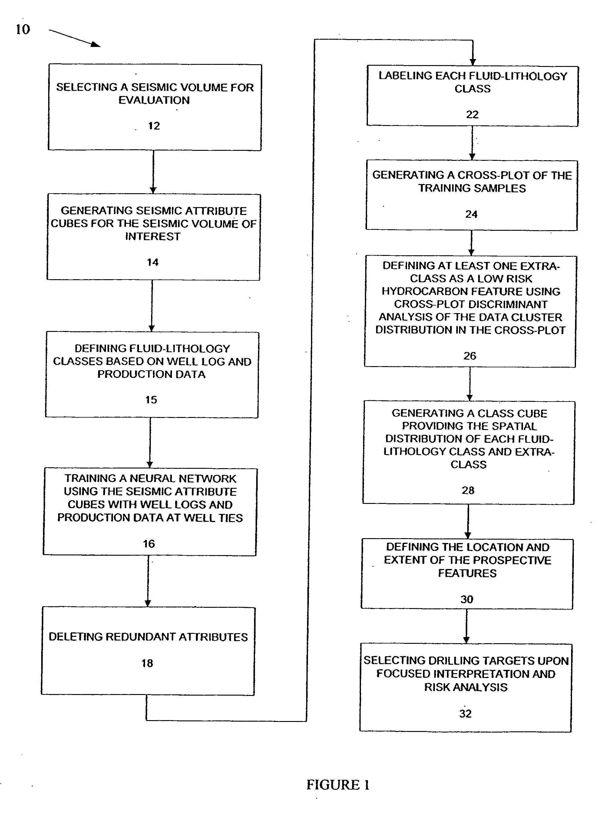
[0026]FIG. 1 is a flow diagram of a 3D seismic classification method for prospect identification in asset evaluation of the present invention generally designated by the numeral 10.

[0027] The first step 12 in the 3D classification method 10 is to select a seismic volume for evaluation. For purpose of description and understanding of the various Figures, an existing seismic cube covering two hydrocarbon fields in onshore South Louisiana is chosen for illustration of the present method. The seismic cube covers approximately fifty square miles surrounding the two existing fields. Production is predominantly oil with more than 30 production zones ranging in depth from 8,000 feet to 13,500 feet. 3D classification method 10 is utilized to identify top prospective targets within and adjace...


PUM


Abstract

3D seismic classification is a breakthrough technology to determine the three-dimensional distribution of pore fluid, lithology, and faults/fractures from multiple seismic attribute volumes. This method provides an innovative, timesaving solution for identification and definition of drilling targets, especially in areas with multiple pay zones and complex geology.

Description

RELATED APPLICATIONS [0001] This application claims benefit of priority from U.S. Provisional Application No. 60 / 472,620, filed May 22, 2003 and entitled IDENTIFYING PROSPECTIVE TARGETS, which is incorporated by reference herein.FIELD OF THE INVENTION [0002] The present invention relates in general to the field of seismic data interpretation and, more specifically, to the determination of 3D distribution of pore fluid and lithology from multiple seismic attribute volumes for identifying prospects in asset evaluation. BACKGROUND [0003] Identification of prospective targets for hydrocarbon exploration and production opportunities in asset evaluation generally requires months of seismic interpretation to tie well production zones, interpret the horizons of interest, extract and analyze seismic attributes corresponding to petrophysical properties, and assess the potential and risks. [0004] Generally in traditional seismic interpretation, one or more seismic events are identified and tra...

Claims


Application Information

Patent Timeline
IPC IPC(8): G01V1/30G01V1/32
CPCG01V1/32G01V1/30G01V1/302
Inventor XUE, FANGJIAN
Owner SCHLUMBERGER TECH CORP
Why Eureka
Try Eureka