Air cooling device

a cooling device and air technology, applied in the field of air cooling devices, can solve the problems of air conditioners that are undesirable, heavy, expensive and complex, and anything that adds weight to the aircraft, reducing the performance and payload of the aircra

Inactive Publication Date: 2005-01-27
BLACKSTONE RALF W
View PDF21 Cites 32 Cited by
  • Summary
  • Abstract
  • Description
  • Claims
  • Application Information

AI Technical Summary

Benefits of technology

[0009] Applicant provides to these and other objects by providing a small inexpensive lightweight air distribution cooler distribution system for a vehicle that is powered by the vehicle's electrical system.

Problems solved by technology

On the other hand, one gram of water will release 540 calories of heat when changing from water vapor at 100° C. to liquid water at 100° C. Air conditioners, however, are heavy, expensive and complex.
Air conditioners are undesirable, for example, in cooling a cabin of a small or light aircraft such as a 2, 4 or 6 place airplane.
In such light aircraft, there is a fairly small cabin space and anything that adds weight to the aircraft decreases its performance and payload.
Thus, many light aircraft do not have air conditioning systems.
Moreover, complicating this deficiency is the often limited ability to move air between the outside and the inside of the aircraft via ducts or windows.
Thus, it may often get quite warm in the small interior cabin space of a light aircraft, especially when it is parked or tied down for a period of time on an airport apron.
The warm air cabin environment of a light aircraft is not conducive to the concentration required for the pilot to operate the aircraft, especially during critical take-off or landing procedures.
However, this does not help when the aircraft has been sitting for a period of time in the hot air on the ground.

Method used


Image

  • Air cooling device
  • Air cooling device
  • Air cooling device

Examples


Embodiment Construction

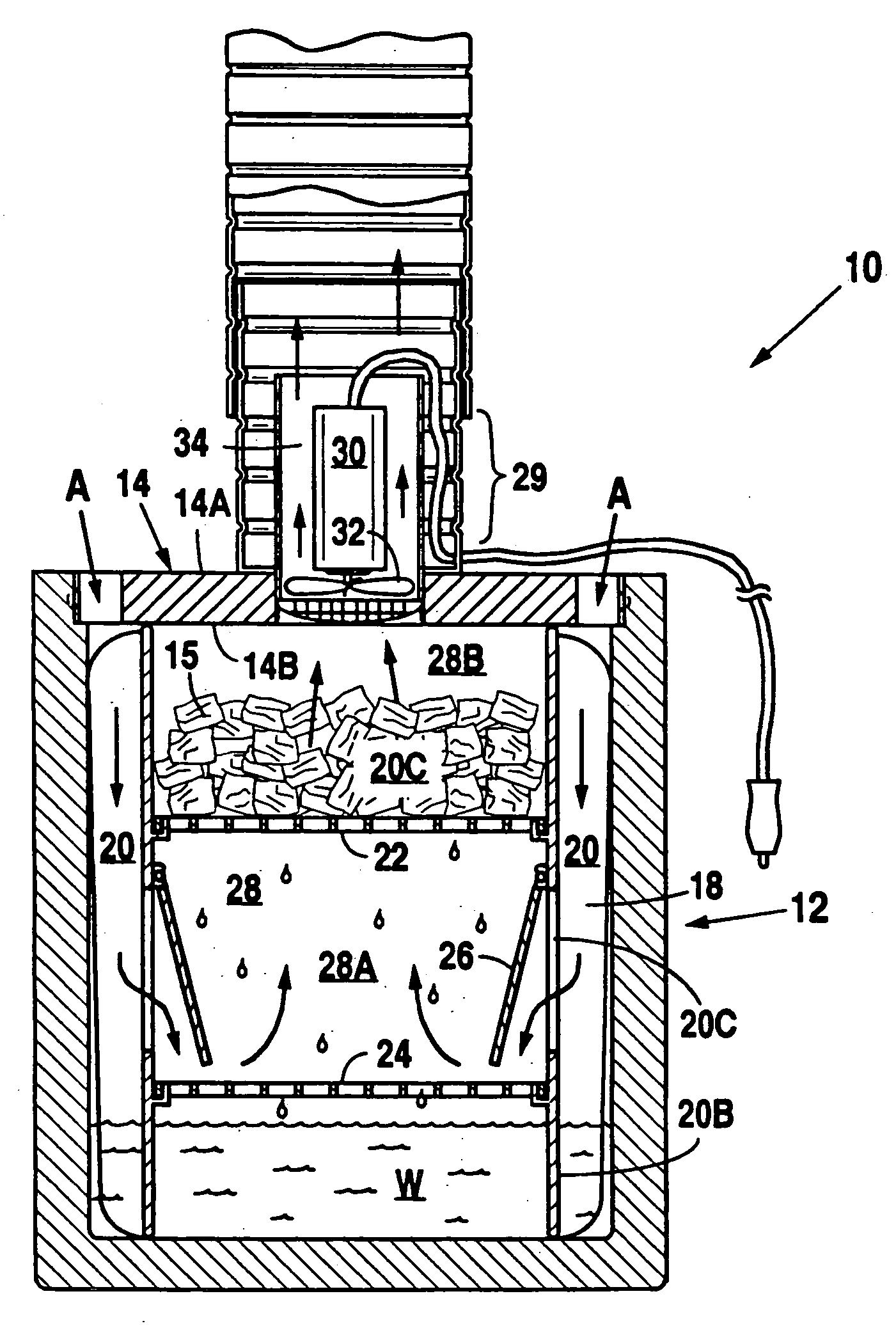
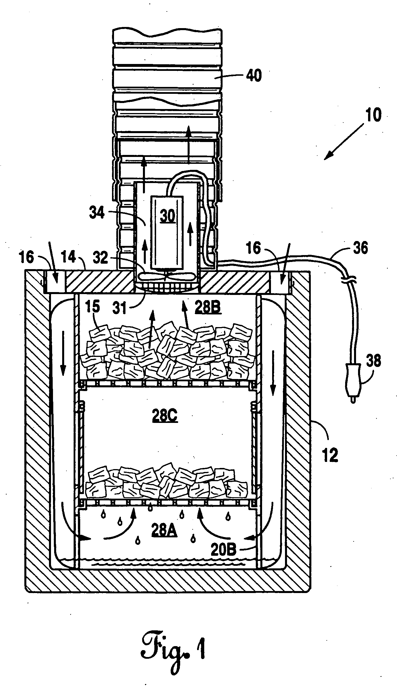
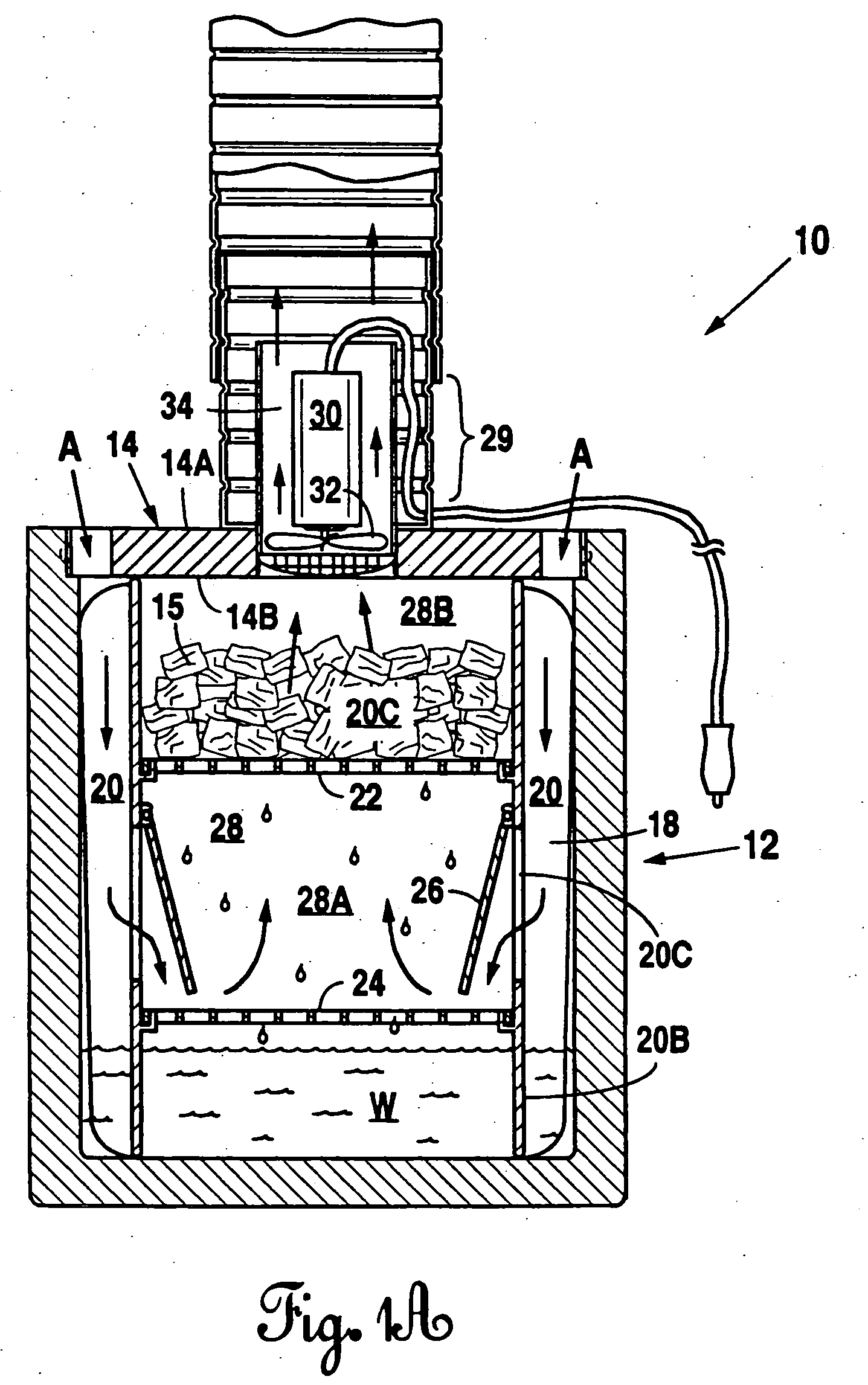
[0062] A first embodiment of Applicant's novel heat reduction device (10) is found in FIGS. 1, 1A, 1B and 2. With reference to these figures and those that follow, it is seen that Applicant provides a heat reduction system (10) comprising an insulated container, typically a six sided rectangular box (12), the box including a lid (14), typically insulated. The walls of the box (12) including where the removable lid (14) is fitted as part thereof are sealed except as provided with the vents, etc., as set forth below. The box (12) may be manufactured from one or more of the following: plastic, foam or any other suitable insulating material. The box may have any number of shapes including the rectangular shape illustrated. Typical dimensions for a rectangular box are approximately 15″ in width, 17″ in height and.

[0063] Applicant's novel invention includes providing for placement within the box (12) (typically by removing the lid and placing it therein), an endothermic substrate (15). T...


PUM


Abstract

A vest including inflatable tubes or chambers which receive cool air from a blower box. The vest includes an outer surface and inner surface, the two surfaces joined to define a multiplicity of tubes. The tubes carry jets which may vent cool air, received from a remote cool air blower box. The jets will ventilate the skin of the wearer both where it is exposed and where the skin is covered by the garment itself.

Description

[0001] This application claims priority from, incorporates by reference, and is a continuation in part of U.S. patent application Ser. No. 10 / 640,347, filed Aug. 13, 2003, which is a continuation in part of U.S. patent application Ser. No. 10 / 453,437, filed Jun. 3, 2003, which is a continuation in part of U.S. patent application Ser. No. 10 / 375,526, filed Feb. 27, 2003, which is a continuation in part of U.S. patent application Ser. No. 09 / 886,588 (now U.S. Pat. No. 6,571,574), filed Jun. 21, 2001 and claims priority from provisional patent application 60 / 212,949 filed Jun. 21, 2000.FIELD OF THE INVENTION [0002] Air cooling devices, more specifically, an air cooling device comprising an endothermic substrate bearing container with an air circulation means for circulating air from outside the container, about the endothermic substrate and, chilled, exhausted from the container. BACKGROUND [0003] Humans can function optimally, in comfort, over only a fairly narrow ambient temperature ...

Claims


Application Information

Patent Timeline
Patent Type & Authority Applications(United States)
IPC IPC(8): A41D13/002B60H1/32F24F5/00
CPCA41D13/0025B60H1/3235Y02E60/147F24F2221/38F24F5/0017Y02E60/14
Inventor BLACKSTONE, RALF W.
Owner BLACKSTONE RALF W
Why Eureka
Try Eureka