Automated machine setup with modular tooling

a technology of automatic machine setup and tooling, which is applied in the direction of shaping tools, programme control, shaping safety devices, etc., can solve the problems of time-consuming process of operator setup and programming, waste of materials, and defective products, and achieve the effect of improving the tooling for use in the host machin

Inactive Publication Date: 2005-01-27
ZUSI CHRISTOPHER J
View PDF24 Cites 33 Cited by
  • Summary
  • Abstract
  • Description
  • Claims
  • Application Information

AI Technical Summary

Problems solved by technology

Due to the complexity of setup and the number of possible applicators involved, setup and programming by an operator can be a time consuming process.
Additionally, if the wrong stripping parameters are set and the machine is allowed to run, defective product may be produced, materials may be wasted and production time may be lost.

Method used


Image

  • Automated machine setup with modular tooling
  • Automated machine setup with modular tooling
  • Automated machine setup with modular tooling

Examples


Embodiment Construction

[0017] U.S. Provisional Patent Application, Application No. 60 / 475,681, titled AUTOMATED TOOLING SETUP IN MODULAR TOOLING, filed Jun. 4, 2003 is hereby incorporated by reference.

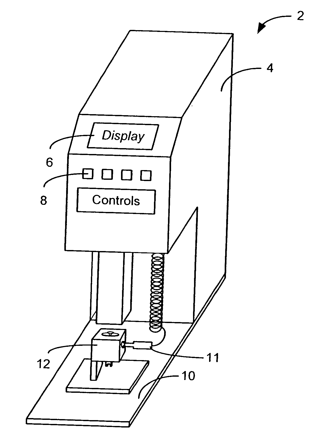
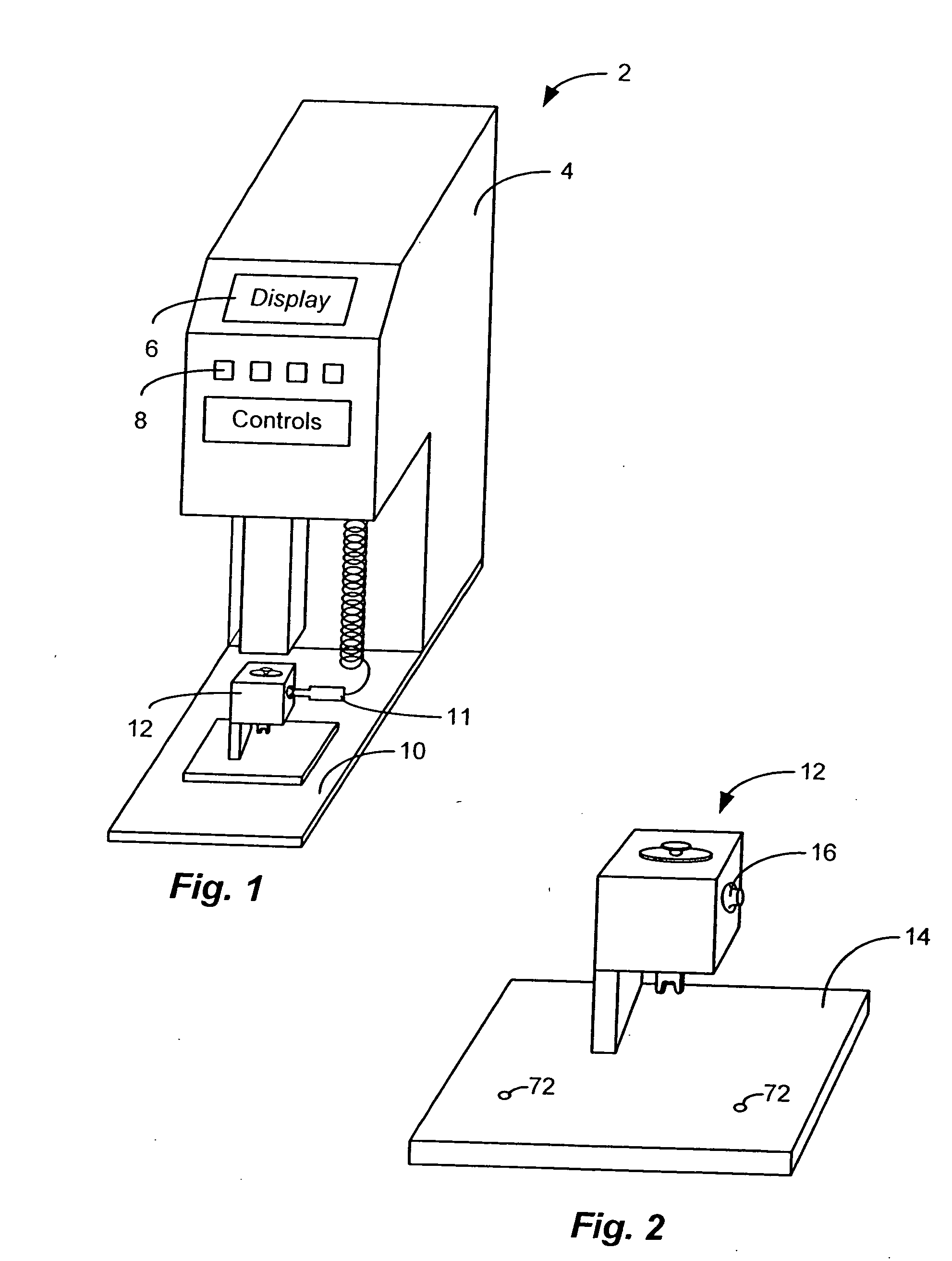
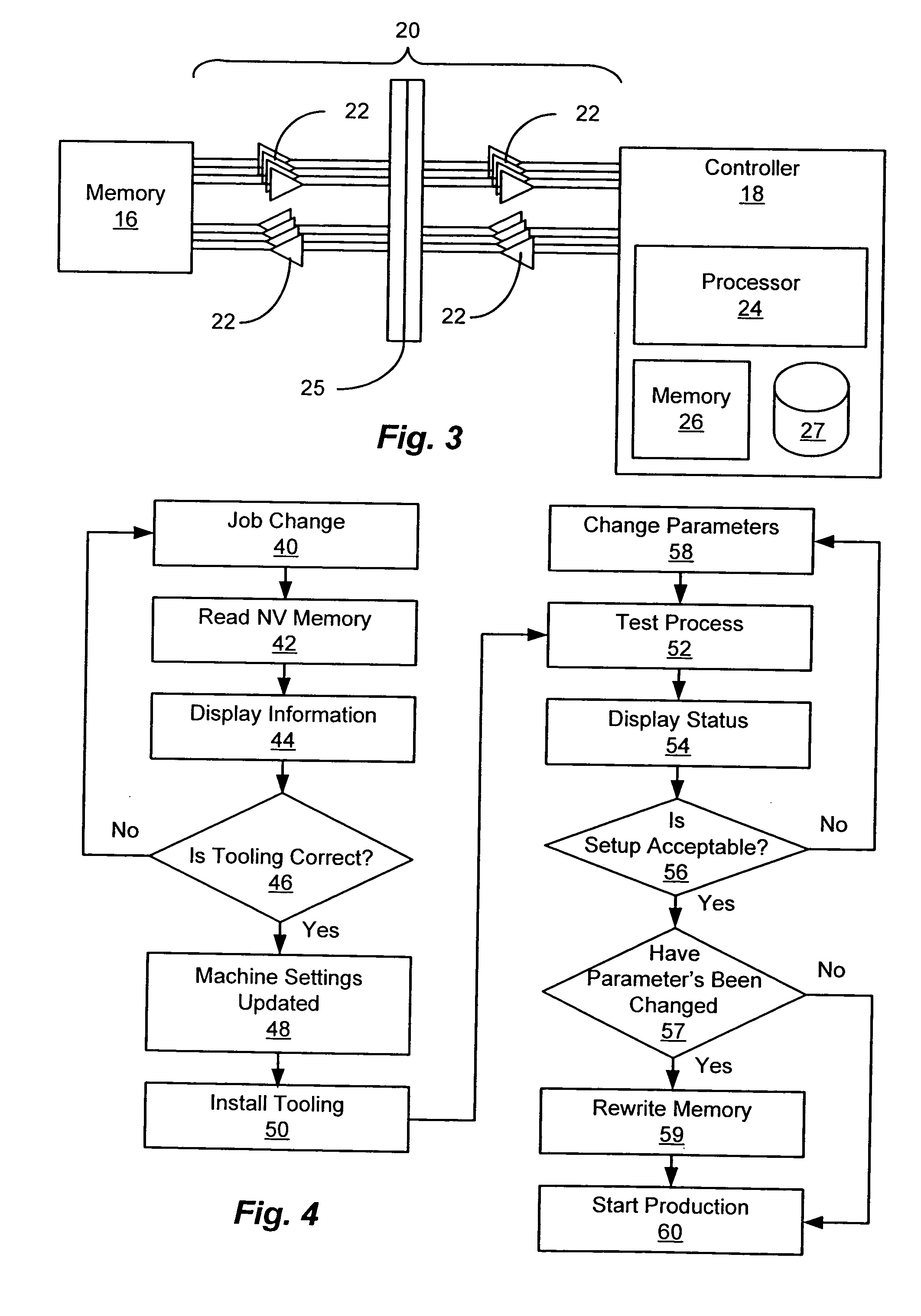
[0018] In accordance with the present invention, an improved removable tooling component for use with a host machine is disclosed. The tooling component facilities rapid and reliable setup of the host machine. The tooling component is removably mountable to the host machine. In one embodiment, a memory is physically associated with the tooling component. The tooling component memory is preferably a non-volatile memory that contains setup parameters for the applicable for use by the host machine with the particular tooling component. The tooling component memory is readable by a controller associated with the host machine. The controller uses the setup parameters read from the memory to configure the host machine for use with the respective component. More specifically, wire processing machines known in the ...


PUM

PropertyMeasurementUnit
conductiveaaaaaaaaaa
radio frequencyaaaaaaaaaa
sizeaaaaaaaaaa

Abstract

Apparatus and a method for establishing setup parameters for use in a machine. In one embodiment a tooling component is removably mountable to a host machine. The tooling component includes a memory that contains information defining setup parameters for the host machine for use with the tooling component. A controller associated with the host machine reads the information from the memory and configures the host machine based on the information read from the memory. In another embodiment, an information carrying tag, is associated with the tooling component. The information carrying tag is read and the identifying information obtained from the tag is used by a controller to select a set of setup parameters from one or more sets of setup parameters stored in a storage device accessible by the controller. A mechanism is provided to precisely position the adapter on the base plate for the host machine to minimize variations in production using the setup parameters derived from the stored information.

Description

CROSS REFERENCE TO RELATED APPLICATIONS [0001] The present application claims priority under 35 U.S.C. 119(e) of U.S. Provisional Patent Application titled AUTOMATED TOOLING SETUP IN MODULAR TOOLING, Application No. 60 / 475,681 filed Jun. 4, 2003.STATEMENT REGARDING FEDERALLY SPONSORED RESEARCH OR DEVELOPMENT [0002] Not Applicable BACKGROUND OF THE INVENTION [0003] The present invention relates generally to machine tooling and more specifically to method and system setting up machine tooling in advance of use. [0004] Crimping a terminal to a wire requires the use of a “crimping die” or “applicator” in conjunction with a press, semi-automatic stripper-crimper, or fully automatic cut-strip-terminate machine. Both the stripper-crimper and the cut-strip-terminate machines incorporate mechanisms to strip wire insulation prior to actuating the applicator to produce a completed wire termination. Removing the wire's insulation or “stripping” has specific parameters that need to be set in ord...

Claims


Application Information

Patent Timeline
Patent Type & Authority Applications(United States)
IPC IPC(8): B21D37/00G06F
CPCG05B19/128G05B2219/49304G05B2219/49305Y10T29/49185Y10S72/712Y10T29/53235Y10T29/49192H01R43/048B30B15/26Y02P90/80
Inventor ZUSI, CHRISTOPHER J.
Owner ZUSI CHRISTOPHER J
Why Eureka
Try Eureka