Color-space transformation-matrix calculating system and calculating method

a color space and matrix technology, applied in the field of color adjustment methods, can solve the problems of inability to reproduce the original color of the object, disadvantages of rgb signal based reproduction, poor reproducibility of rgb signal based methods, etc., and achieve the effect of accurately reproducing the original color

Inactive Publication Date: 2005-01-27
HOYA CORP
View PDF7 Cites 74 Cited by
  • Summary
  • Abstract
  • Description
  • Claims
  • Application Information

AI Technical Summary

Benefits of technology

Therefore, an object of the present invention is to provide a color space transformation matrix that has the advantage of accurately reproducing an original color, particularly in regard to hue.

Problems solved by technology

Further, the images reproduced by the image output device are also different from one another in regard to how they are reproduced even when the same RGB signals are supplied.
Therefore the reproduction of a color image based on the RGB signals is disadvantageous for reproducing the original color of the object.
Therefore, the RGB signal based method is poor for reproducing precise color.
However, the relations between the RGB signals and the hue are not linear relations, therefore, the evaluation of accuracy for the above discussed multiple linear regression analysis is difficult.

Method used


Image

  • Color-space transformation-matrix calculating system and calculating method
  • Color-space transformation-matrix calculating system and calculating method
  • Color-space transformation-matrix calculating system and calculating method

Examples


first embodiment

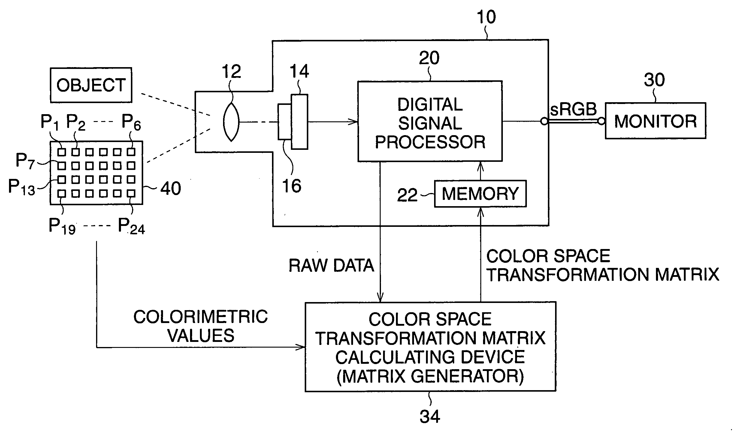
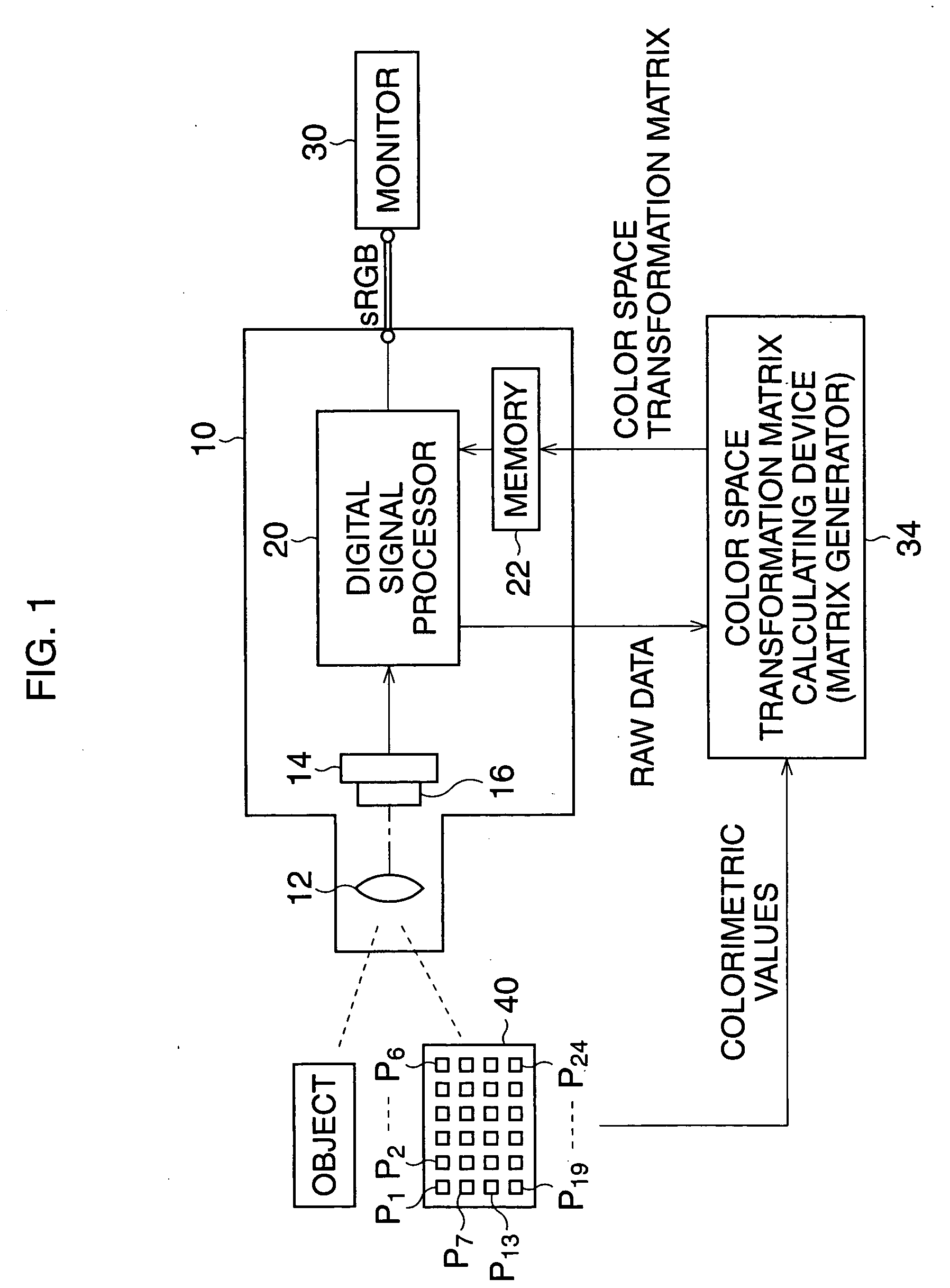
FIG. 1 schematically illustrates a first embodiment and shows how the color space transformation matrix is calculated and the method for color transformation, in the present embodiment.

The digital still camera 10 is an example of an image input device that captures a full color image of an object by using an imaging device. The digital still camera 10 includes an imaging optical system 12 and an imaging device, such as a CCD 14. The CCD 14, for example, is provided with an RGB color chip filter 16 which is mounted in front of the imaging surface of the CCD 14. An optical image produced on the imaging device, through the imaging optical system 12, is subjected to photoelectrical conversion by the CCD 14 and output therefrom as analog signals. The output analog signals are then subjected to analog signal processes and A / D conversion. Thereby the digital image signals are fed to a digital signal processor 20 as one frame of RAW data.

The digital signal processor 20, carries out a colo...


PUM

PropertyMeasurementUnit
color temperatureaaaaaaaaaa
color spaceaaaaaaaaaa
coloraaaaaaaaaa

Abstract

A color space transformation matrix calculating system is provided that optimizes a color space transformation matrix. The matrix is obtained as a product of a first and a second matrix and transforms colors in a first color space to colors in a second color space. The system comprises first and second optimizers that calculate elements of the first matrix and second matrix by multiple linear regression analysis. The input colors which correspond to color patches and hue corrected colors obtained by using the first matrix and the input colors are set as explanatory variables. First and second goal colors respectively relating to hue and saturation in a second color space, and which correspond to the color patches, are set as criterion variables. The elements of matrices are set as partial regression coefficients.

Description

BACKGROUND OF THE INVENTION 1. Field of the Invention The present invention relates to a color adjusting method that optimizes color signals to improve the reproduction of a color image of an object. Further, the present invention relates to a color-space transformation-matrix calculation method that optimizes matrix elements for adjusting color signals. 2. Description of the Related Art In recent years, it has become popular to digitalize images for convenience of transmitting the image information precisely between different types of devices. For example, an image input device, such as a digital camera, an image scanner, and so on, transform color images of an object to signals representing the three primary colors, such as RGB signals, and then output the signals to an image output device, such as a monitor, a printer, and the like. Generally, the image output device reproduces the color image in accordance with the RGB signals, i.e. indicating an image on a screen or printin...

Claims


Application Information

Patent Timeline
Patent Type & Authority Applications(United States)
IPC IPC(8): G03F3/08G06F15/00H04N1/60
CPCH04N1/6033
Inventor CHIBA, TORU
Owner HOYA CORP
Why Eureka
Try Eureka