Flexible substrate and electronic device

a flexible substrate and electronic device technology, applied in the direction of printed circuit aspects, electrical apparatus casings/cabinets/drawers, support structure mounting, etc., can solve the problems of inconvenient limitation, complicated flexible substrate manufacturing process, low flexibility of flexible substrate, etc., and achieve the effect of high durability against repetitive bending

Inactive Publication Date: 2005-01-27
LENOVO INNOVATIONS LTD HONG KONG
View PDF5 Cites 52 Cited by
  • Summary
  • Abstract
  • Description
  • Claims
  • Application Information

AI Technical Summary

Benefits of technology

[0060] A flexible substrate according to the present invention has high durability against repetitive bending and is applicable to portable terminals and other electronic devices with advanced functions.

Problems solved by technology

The structure according to the patent application cited above thus complicates the flexible substrate manufacturing process and lowers the productivity of the flexible substrate.
The limitation is inconvenient when the width of the power supply line (wiring conductor) which is set such that the current resistance of the power supply line does not exceed a predetermined level has to be changed (increased) in order to prevent power consumption from exceeding a predetermined level.
Since the slit interval limits the width of the power supply line (wiring conductor) to a given width or smaller in the structure according to the patent application cited above, the permissible current is exceeded making it impossible to flow an appropriate current in the wiring conductor.
This means that the maximum width of the flexible substrate is limited by the internal diameter of the hinge, and that the flexible substrate cannot have a necessary number of signal lines when the width of the power supply line is set large.
Another problem of the structure according to JP 2002-158458 A is that it is difficult in practice to form slits, each of which has to be 1 mm or more in width, in manufacture of the flexible substrate whose width is limited to the inner diameter of the hinge.
A reduction in wiring conductor width throughout the entire length of the power supply line 102 (a uniform reduction of the line widths K1 to K3) therefore raises problems such as an increase in current resistance of the power supply line 102 which leads to malfunction by voltage drop.
In conclusion, the structure according to JP 2002-158458 A is not suitable for portable terminals which are demanded to have advanced functions.
The flexible substrate according to JP2002-158458 A cannot provide advanced functions because its insufficient durability against repetitive deploying and folding (bending) of the portable terminal.

Method used


Image

  • Flexible substrate and electronic device
  • Flexible substrate and electronic device
  • Flexible substrate and electronic device

Examples


embodiment 1

[0092] Embodiment 1

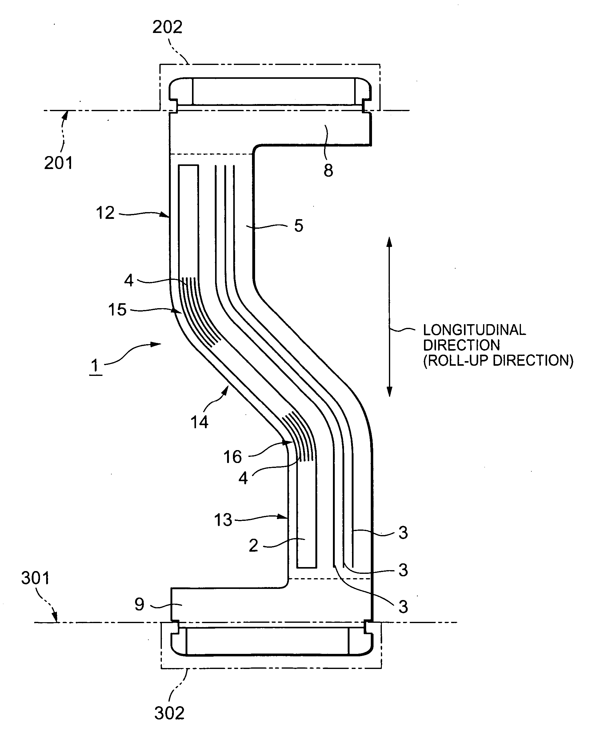
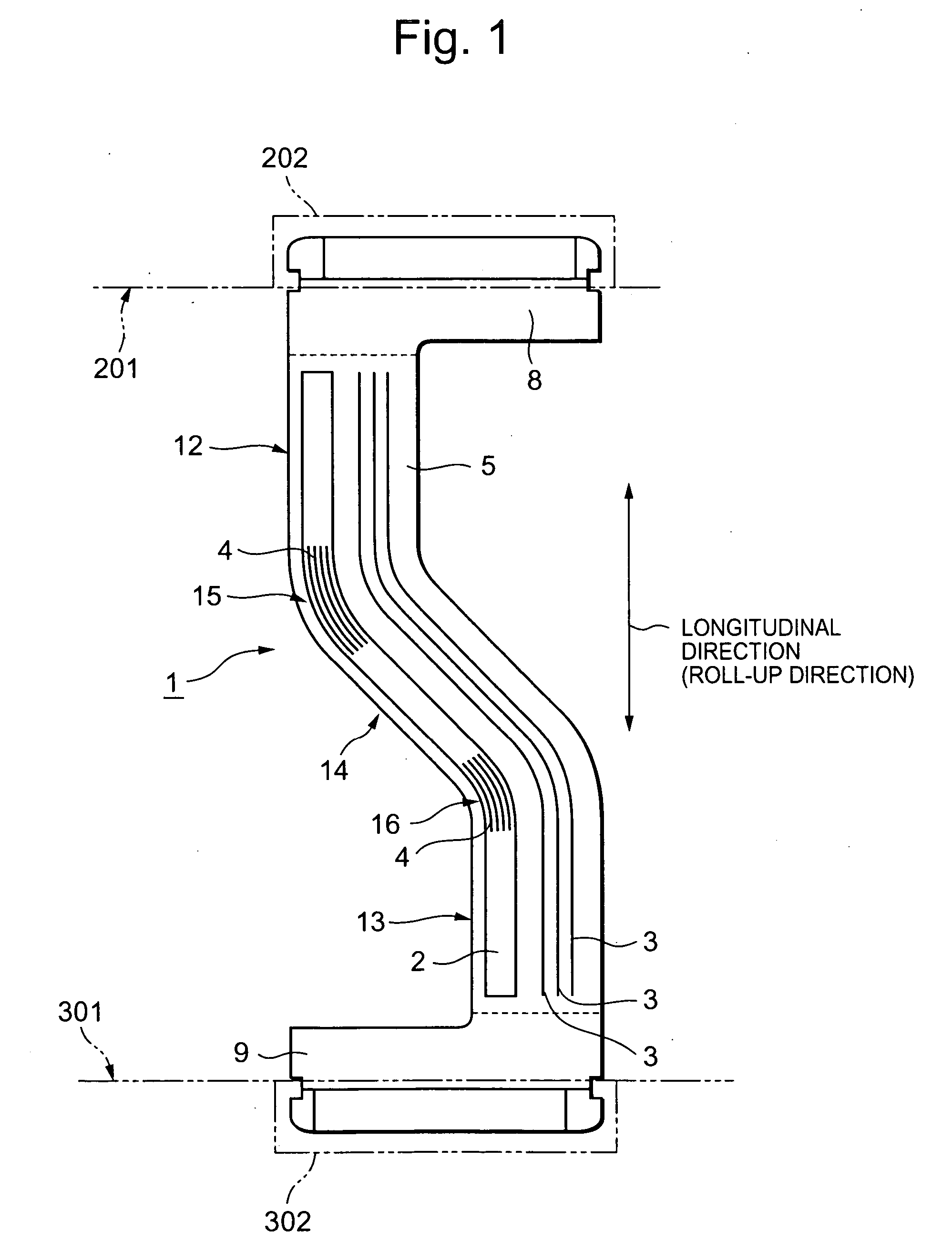
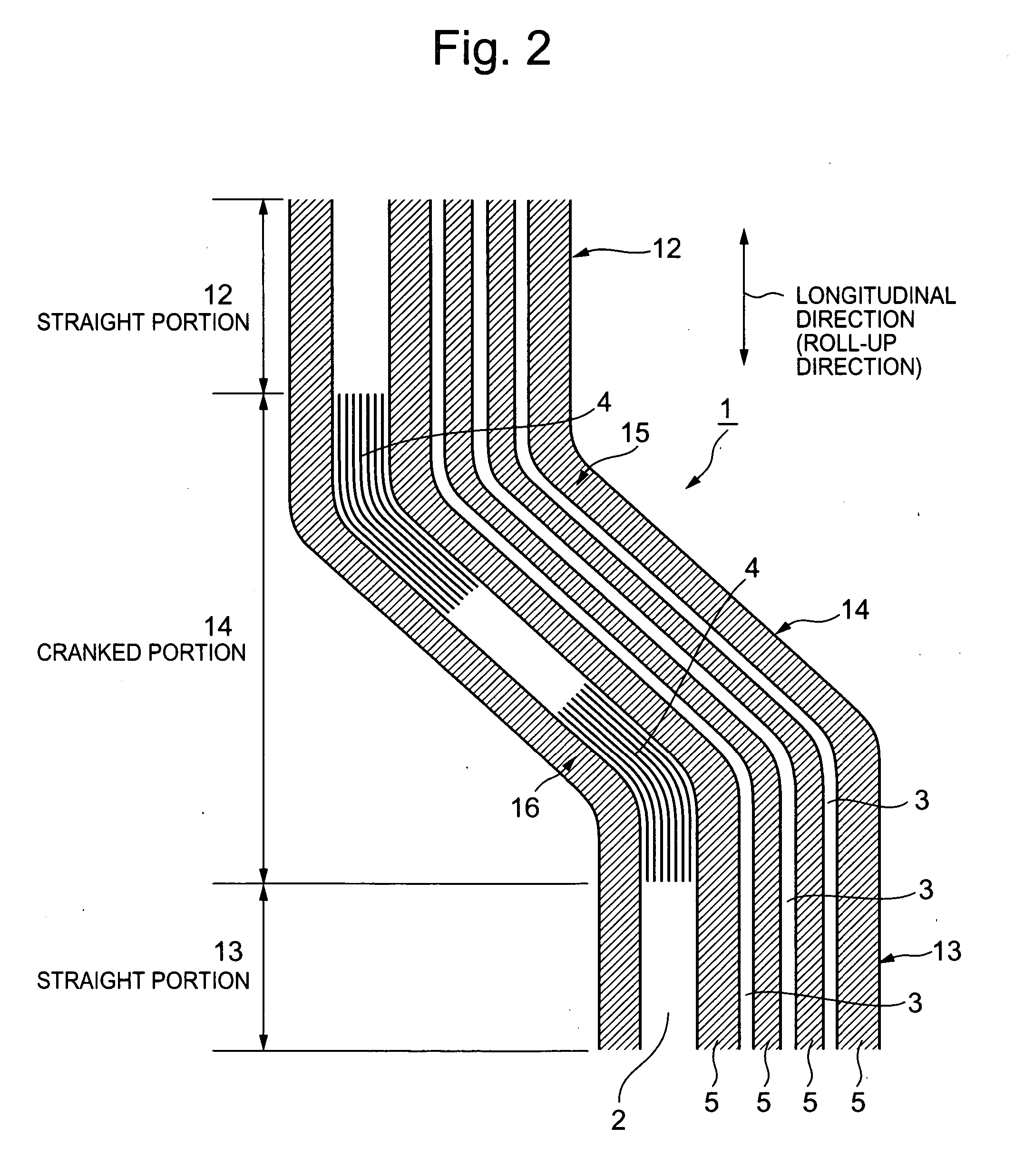
[0093]FIGS. 1 through 4 show a structural example of a flexible substrate 1 according to Embodiment 1. FIG. 1 is a plan view of the flexible substrate. FIG. 2 is a plan view showing an enlarged view of a critical part of the flexible substrate of FIG. 1.

[0094] As shown in FIG. 1, the flexible substrate 1 is larger in length than width. The (elongated) flexible substrate 1 has connection portions 8 and 9, which are end portions of the substrate, straight portions 12 and 13, which are extension portions, and a cranked portion 14, which is a bent portion, and is unitarily formed.

[0095] As shown in FIG. 2, the cranked portion 14 is composed of, portions extended from the straight portions 12 and 13, angled portions continued from the portions extended from the straight portions 12 and 13, and a linear portion formed between the angled portions in a direction oblique to the longitudinal direction of the flexible substrate 1.

[0096] As shown in FIG. 1, the connection ...

embodiment 2

[0120] Embodiment 2

[0121] Embodiment 2 of the present invention is described with reference to FIGS. 5 through 9. A flexible substrate 17 according to this embodiment is obtained by overlapping two flexible substrates, namely, a first flexible substrate (hereinafter referred to simply as first substrate) 18 and a second flexible substrate (hereinafter shortened as second substrate) 19.

[0122] As shown in FIG. 5, the first substrate 18 has the same structure as the flexible substrate 1 of Embodiment 1. The first substrate 18 therefore includes connection portions, straight portions 22 and 23, and a cranked portion 24. The connection portions of the first substrate 18 correspond to the connection portions 8 and 9 of the flexible substrate 1 shown in FIG. 1, and hereinafter are denoted by the same symbols, 8 and 9, as their counterparts in FIG. 1.

[0123] One power supply line 52 and plural signal lines 53 are arranged on the front side of the straight portions 22 and 23 and the cranked...

embodiment 3

[0151] Embodiment 3

[0152] Embodiment 3 of the present invention is described with reference to FIGS. 10 through 13. As shown in FIG. 13, a flexible substrate 70 according to this embodiment has a base 81 which has lines of wiring conductors arranged on each side thereof. FIG. 10 is a plan view of the flexible substrate according to this embodiment. FIG. 11 is a rear view of the flexible substrate shown in FIG. 10.

[0153] As shown in FIG. 10, one power supply line 72 and plural signal lines 73 (only three of the signal lines 73 are shown in FIG. 10) are placed on one side of the base 81. As shown in FIG. 11, plural signal lines 76 (only three of the signal lines 76 are shown in FIG. 11) and plural overlapping signal lines 77 (only two of the overlapping signal lines 77 are shown in FIG. 11) are arranged on the other side of the base 82. The power supply line 72 and the signal lines 73 in FIG. 10 are indicated by outlined areas. The signal lines 76, 77 in FIG. 11 are indicated by outl...


PUM


Abstract

A flexible substrate inserted in a hinge electrically connects circuit substrates, which are housed in a first casing and a second casing, respectively, to each other. The substrate has a power supply line and signal lines which are formed from a wiring conductor. Slits are opened in border portions of the power supply line in a cranked portion. The slits opened in the border portions of the power supply line make the rigidity of the border portions lower than in prior art. This means that a base is prevented from squashing the wiring conductor (power supply line) when the substrate is bent and that stress concentration on the border portions can accordingly be avoided. As a result, cracks in the border portions are prevented and the power supply line (wiring conductor) is protected against wire breakage.

Description

BACKGROUND OF THE INVENTION [0001] 1. Field of the Invention [0002] The present invention relates to a flexible substrate in which a wiring conductor is arranged from one end to the other end and to an electronic device having this flexible substrate, for example, a portable terminal (cellular phone). More specifically, the invention relates to a foldable (opening / closing) electronic device which is repeatedly folded (closed) and deployed (opened) and to a flexible substrate for electrically connecting circuit substrates to each other which are arranged in a pair of casings in this electronic device. [0003] 2. Description of the Related Art [0004] (Outline of Cellular Phone Structure) [0005]FIG. 14 shows the schematic structure of a folding portable terminal S. In the portable terminal S, a first casing 200 and a second casing 300 are joined to each other through a hinge 400. [0006] The first casing 200 has plural operation keys and others. A detachable battery (omitted from the dra...

Claims


Application Information

Patent Timeline
Patent Type & Authority Applications(United States)
IPC IPC(8): H05K1/00
CPCH05K1/028H05K2201/09727H05K2201/0969
Inventor HIRAKATA, NOBUYUKI
Owner LENOVO INNOVATIONS LTD HONG KONG
Why Eureka
Try Eureka