
Multiple array surface plasmon resonance biosensor

Active Publication Date: 2005-01-27
CYTEK BIOSCI
View PDF4 Cites 59 Cited by
  • Summary
  • Abstract
  • Description
  • Claims
  • Application Information

AI Technical Summary

Benefits of technology

[0013] Accordingly, the present invention provides a highly sensitive waveguide sensor capable of measuring one

Problems solved by technology

Free space SPR interferometry techniques, such as SPR ellipsometry, optical heterodyning, and mapping the spatial intensity distribution, are cumbersome to be incorporated into compact SPR devices and exhibit high sensitivity to changes in the environment, such as temperature fluctuations.

Method used


Image

  • Multiple array surface plasmon resonance biosensor
  • Multiple array surface plasmon resonance biosensor
  • Multiple array surface plasmon resonance biosensor

Examples


Embodiment Construction

[0026] The detailed description of the specific embodiments, together with the general description of the invention, serves to explain the principles of the invention.

[0027] Unless otherwise indicated, all numbers expressing quantities of ingredients, constituents, reaction conditions and so forth are to be understood as being modified in all instances by the term “about”. Accordingly, unless indicated to the contrary, the numerical parameters set forth in the specification are approximations that may vary depending upon the desired properties sought to be obtained by the subject matter presented herein. At the very least, and not as an attempt to limit the application of the doctrine of equivalents, each numerical parameter should at least be construed in light of the number of reported significant digits and by applying ordinary rounding techniques. Notwithstanding that the numerical ranges and parameters setting forth the broad scope of the subject matter presented herein are ap...


PUM


Abstract

An integrated optical waveguide based surface plasmon resonance biosensor is formed by detecting amplitude and phase of electromagnetic waves utilizing interferometry and / or optical delay configurations.

Description

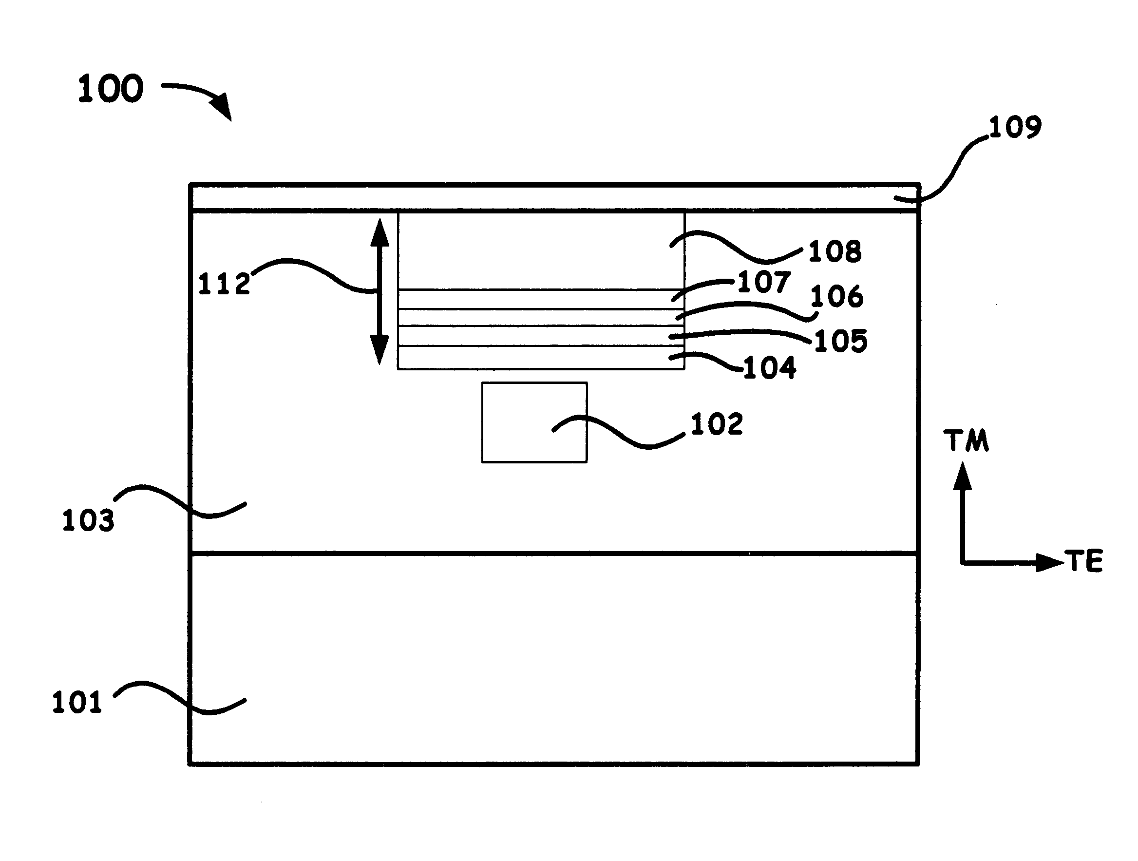
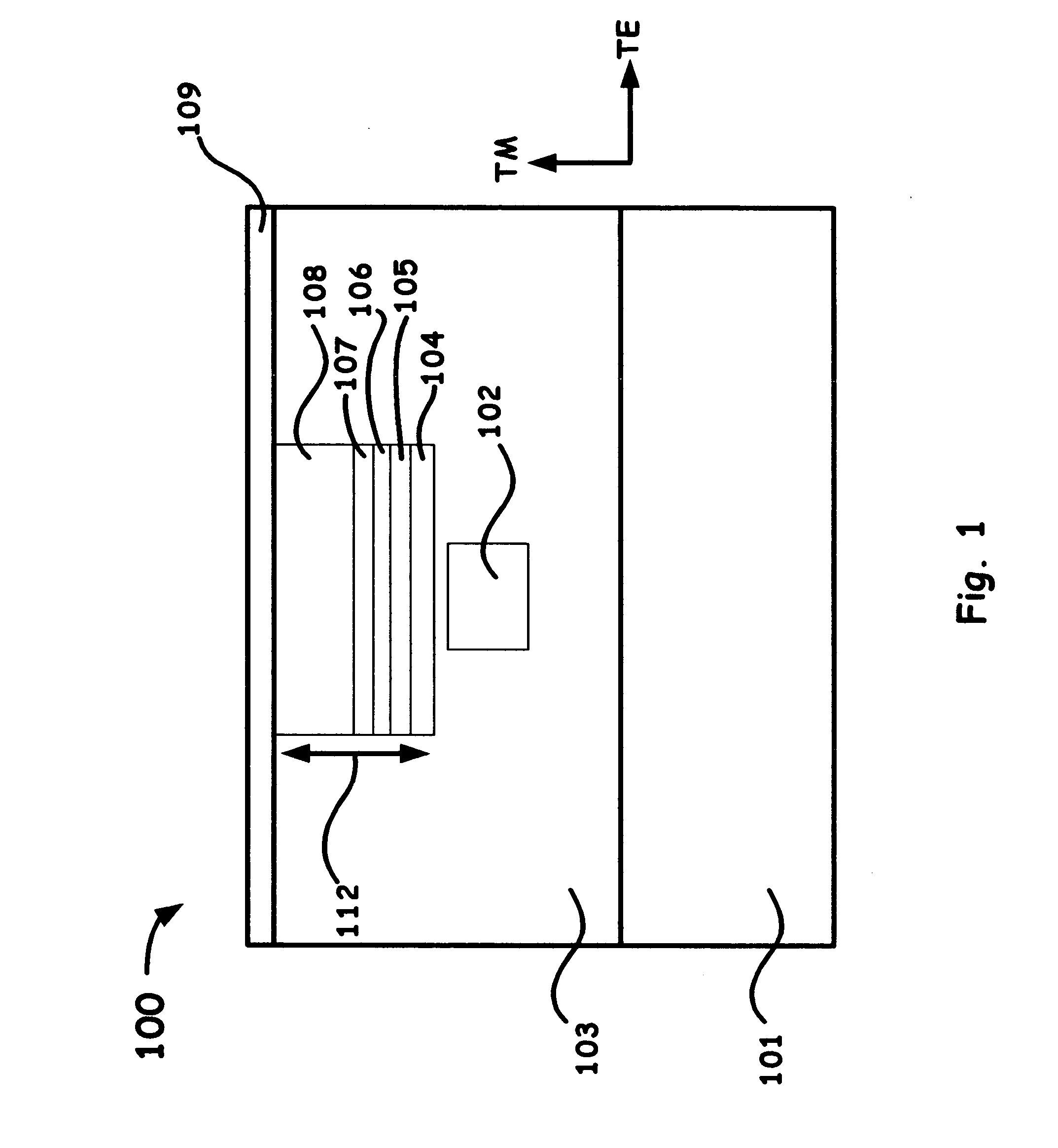
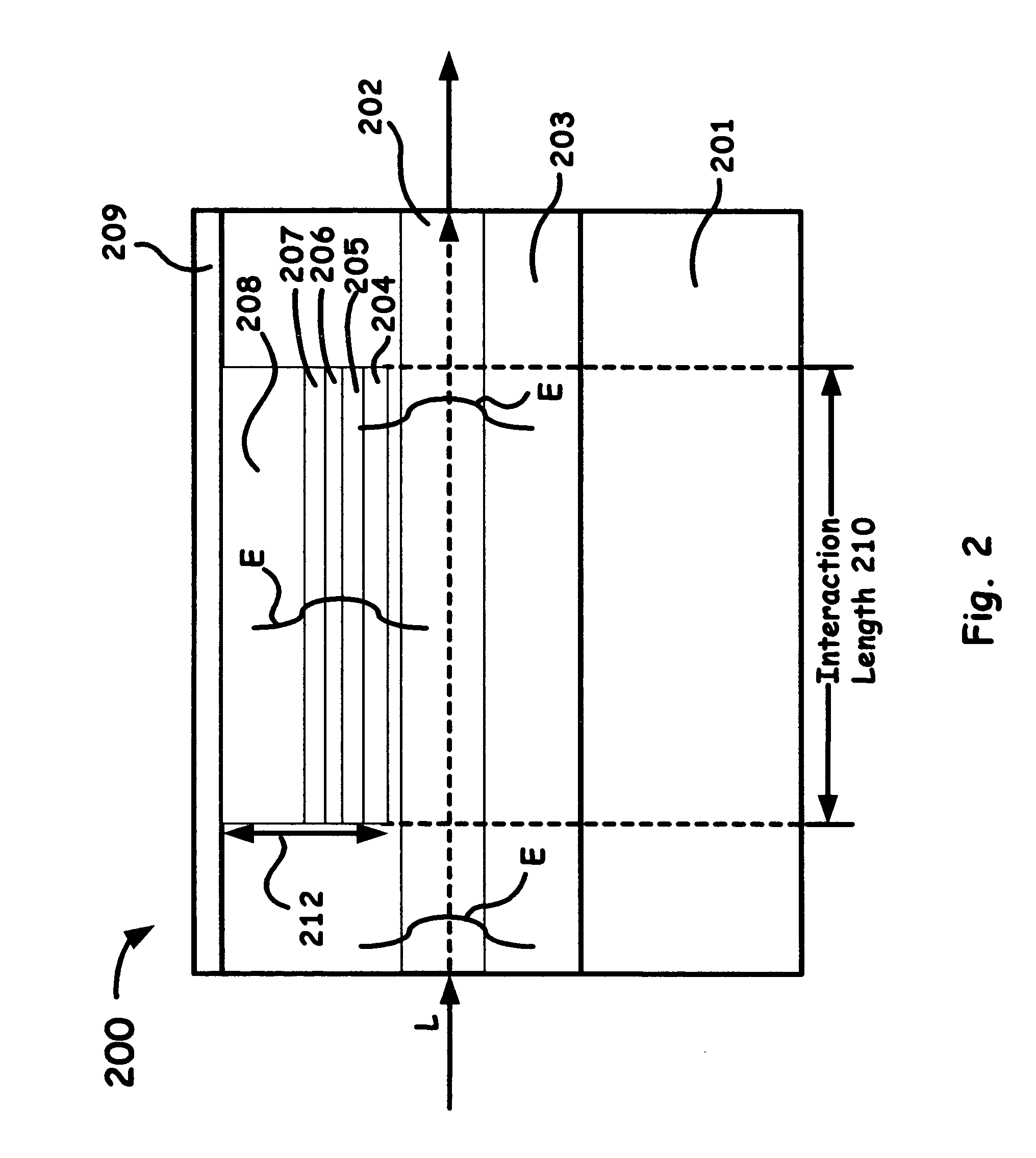
RELATED APPLICATION [0001] This application claims the benefit of U.S. Provisional Application No. 60 / 424966, filed Nov. 8, 2002, and entitled, “Multiple Array Surface Plasmon Resonance Biosensor,” which is incorporated herein by this reference.BACKGROUND OF THE INVENTION [0002] 1. Field of the Invention [0003] The present invention relates to biosensors based on integrated optical waveguides, and more particularly, to surface plasmon resonance interferometric detection sensors formed by an array of planar waveguides. [0004] 2. Description of Related Art [0005] Surface plasmon resonance (SPR) devices have shown high sensitivity in the detection of chemical and biological agents. Conventional SPR devices are based on sensing the reflectance change of mono- or polychromatic light, which undergoes total internal reflection at the hypotenuse of a prism, which is coated with a thin metal film. At certain angles of incidence for a given wavelength of light, the incident light with polariz...

Claims


Application Information

Patent Timeline
IPC IPC(8): G01N21/55G02B6/122
CPCB82Y20/00G01N21/253G01N21/553G02B6/1226G01N33/54373G01N2021/7779G01N21/7703
Inventor YAN, MING
Owner CYTEK BIOSCI
Learn More