Cutting head for rotary cutting tool

a cutting head and cutting tool technology, applied in the direction of shaping cutters, cutting inserts, manufacturing tools, etc., can solve the problems of poor machining performance, reduced rigidity and stability of cutting, and loss of cutting edge accuracy

Active Publication Date: 2005-01-27
ISCAR LTD
View PDF32 Cites 19 Cited by
  • Summary
  • Abstract
  • Description
  • Claims
  • Application Information

AI Technical Summary

Benefits of technology

[0010] In accordance with the present invention, a clamping member urges the clamping portion towards the main body portion thereby creating a clamping force to securely retain the cutting insert in the insert pocket.

Problems solved by technology

In order to perform axial adjustment the locking screw has to be loosened and then tightened after adjustment, as a consequence of which there is a loss of accuracy of the location of the cutting insert's cutting edge as the two parts move away from each other under the influence of gravity.
This reduces rigidity and stability of the cutting insert, especially at high rotational speeds, causing inaccuracies in the location of the insert's operative cutting edge resulting in poor machining performance.
Such forces can also cause bending and even shearing of the securing screw.
These tools, however, are non-rotating tools that can only machine a given diameter circular groove that is dictated by the shape of the support blade of the base jaw.

Method used


Image

  • Cutting head for rotary cutting tool
  • Cutting head for rotary cutting tool
  • Cutting head for rotary cutting tool

Examples


Embodiment Construction

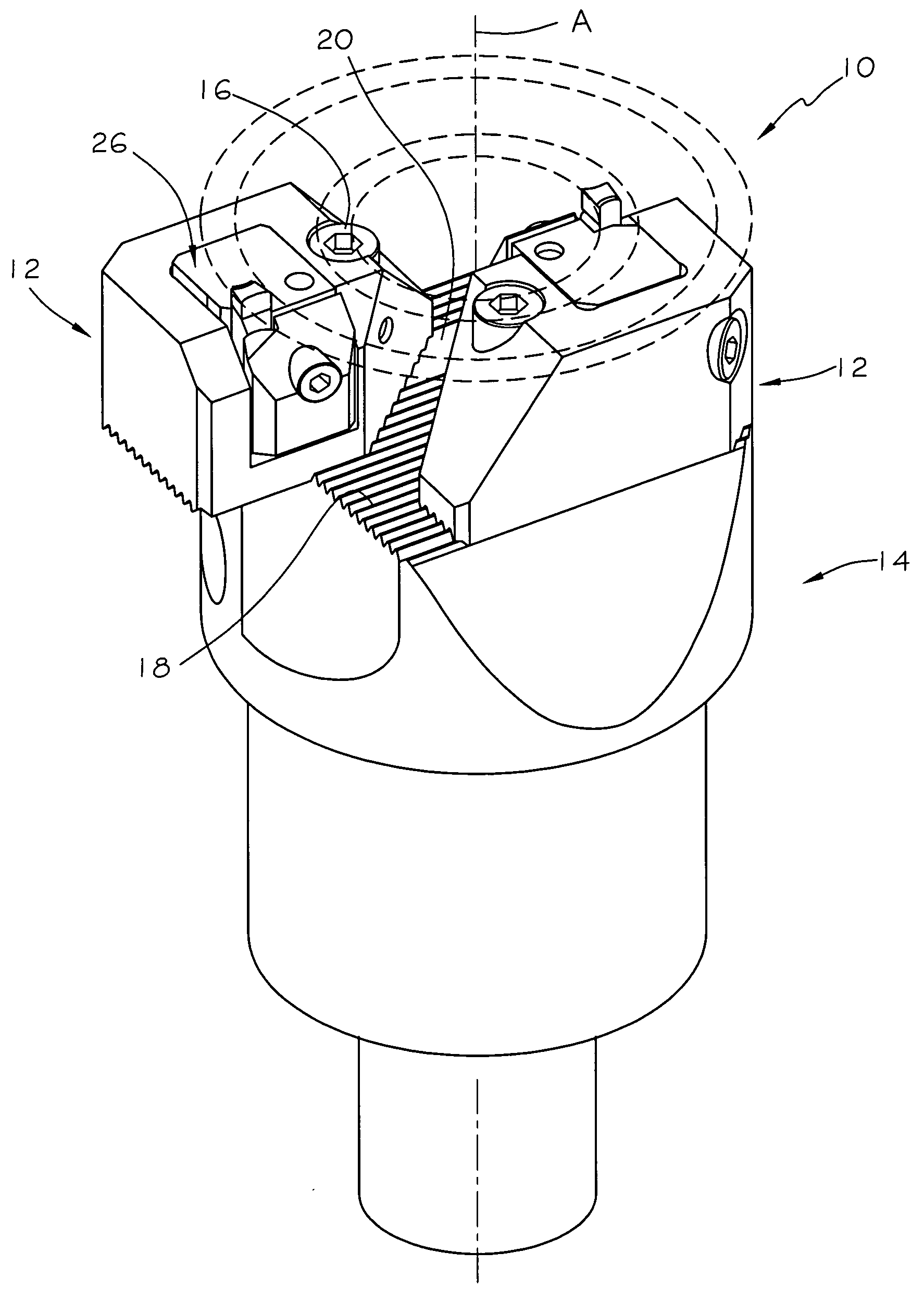
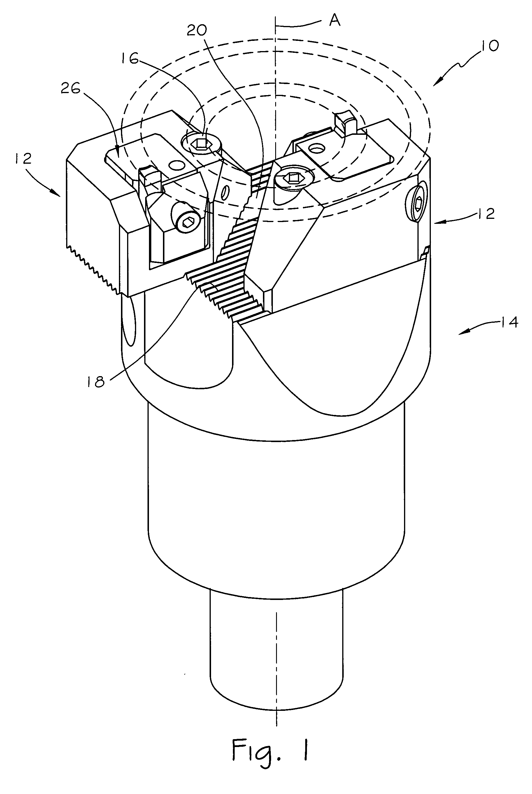
[0028] Attention is first drawn to FIG. 1, showing a rotating metal cutting tool 10 having an axis of rotation A and comprising two cutting heads 12, each cutting head 12 secured to a tool shank 14 by means of a locking screw 16. The shank 14 has an end face 18, perpendicular to the axis of rotation A. The end face 18 is serrated across its entire surface with parallel serrations extending across it, and has two slots 20 (only of which one is partially seen in FIG. 1), each extending parallel to the serrations. In each slot 20, there is a locking nut (not seen) into which the locking screw 16 is threaded, clamping the cutting head 12 to the tool shank 14.

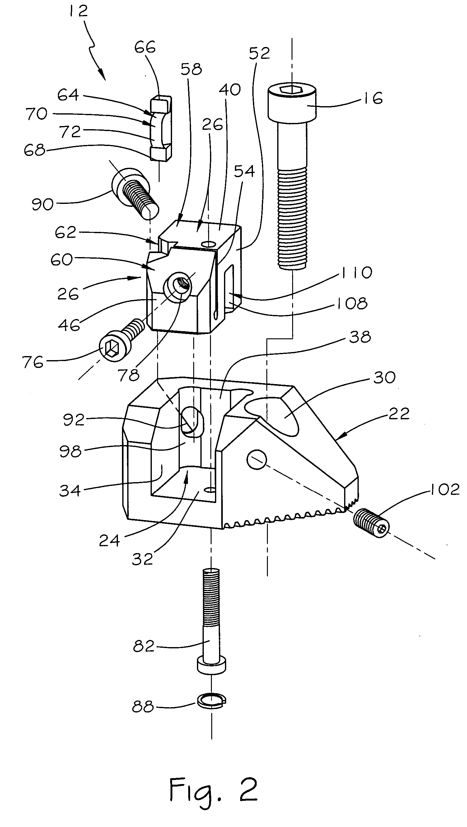
[0029] The cutting head 12 comprises a housing 22 having a recess 24 and an axially adjustable cartridge 26 slidably secured in the recess 24, a serrated mounting surface 28 and a locking through hole 30 extending axially through the housing 22. The serrated mounting surface 28 of the housing 22 meshes with the serrated end face 18...


PUM

PropertyMeasurementUnit
clamping forceaaaaaaaaaa
widthaaaaaaaaaa
depthaaaaaaaaaa

Abstract

A cutting head for a rotating cutting tool for metal cutting operations. The cutting head has an axially adjustable cartridge which is an integral single piece. A slit divides the cartridge into a clamping portion and a main body portion, the clamping portion being resiliently connected to the main body portion. An insert pocket for retaining a cutting insert is formed by a widening of the slit so that the cutting insert is securely retained in the insert pocket between the main body portion and the clamping portion.

Description

FIELD OF THE INVENTION [0001] The present invention relates to rotary cutting tools in general and in particular to rotary face grooving tools for metal working operations of the type in which replaceable cutting inserts are retained in radially and axially adjustable cartridges. BACKGROUND OF THE INVENTION [0002] Such rotary cutting tools are well known in the art and are used for producing at least one circular groove of a given width, depth and diameter in a work-piece by means of one or more cutting inserts, as the cutting inserts rotate around an axis of rotation of the cutting tool. In these applications it is often required to vary the axial and radial location of at least one cutting insert in order to form grooves of differing widths, diameter or depth and in addition sometimes at least one edge of the groove has to be chamfered. Such cutting tools, with adjustable cutting inserts generally comprise a tool body to which insert bearing cartridges are secured. One of the know...

Claims


Application Information

Patent Timeline
Patent Type & Authority Applications(United States)
IPC IPC(8): B23B27/04B23B29/034B23B29/24
CPCB23B27/04B23B29/0341B23B29/248B23B2205/02B23B2260/004Y10T408/86B23B2260/132Y10T407/1932Y10T408/885Y10T408/905Y10T408/8713B23B2260/0045
Inventor ELBAZ, MOSHESHAHIN, HENRI
Owner ISCAR LTD
Why Eureka
Try Eureka