Automatic providing system for inflator

a technology of providing system and inflator, which is applied in the direction of lighting and heating apparatus, explosions, combustion types, etc., can solve the problems of reduced workability and high danger of manual charging

Inactive Publication Date: 2005-01-27
DAICEL CHEM IND LTD
View PDF9 Cites 3 Cited by
  • Summary
  • Abstract
  • Description
  • Claims
  • Application Information

AI Technical Summary

Benefits of technology

[0006] An object of the present invention is to provide an inflator conveying and discharging apparatus and an inflator charging apparatus where charging of inflators can be performed into a thermally treating tower safely and stably, and an automatic charging system of inflators into the thermally treating tower using the same.

Problems solved by technology

When inflators which are treatment subjects are charged into the thermally treating tower, it is desirable to conduct charging by a mechanical means, because it is troublesome to conduct charging manually, which results in reduction of workability, and the manual charging is also high in danger.

Method used


Image

  • Automatic providing system for inflator
  • Automatic providing system for inflator
  • Automatic providing system for inflator

Examples


embodiment 1

[0031] (1) Embodiment 1

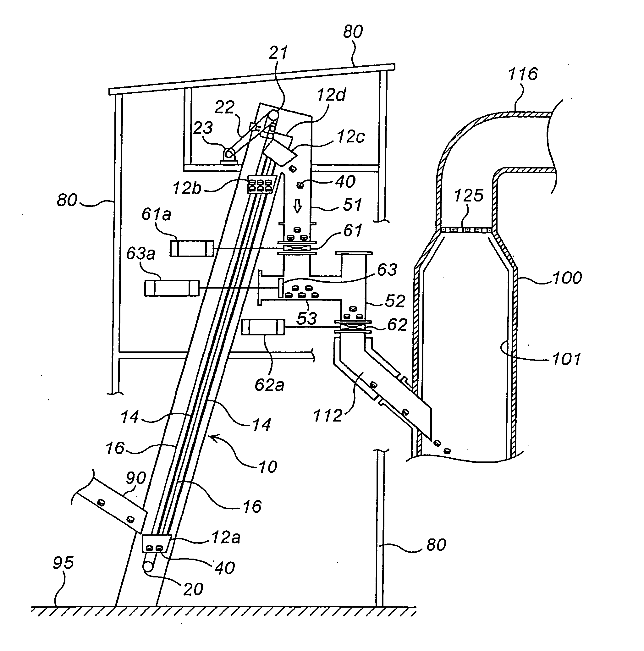
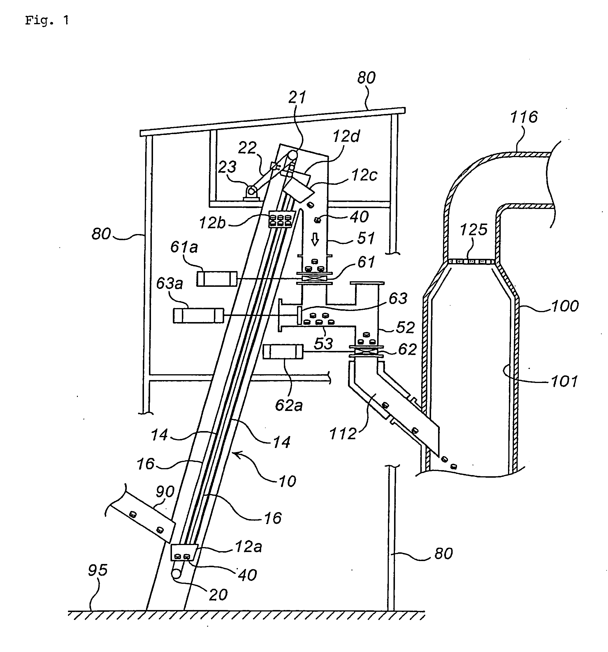
[0032] An inflator conveying and discharging apparatus will be explained with reference to FIG. 1. FIG. 1 is a conceptual diagram of an automatic charging system of inflators into a thermally treating tower combined with an inflator conveying and discharging apparatus.

[0033] A tubular passage 10 is installed to be inclined to an installation surface 95 by a supporting structure 80 formed by combining plural elongated members. An inclination angle of the tubular passage 10 to the installation surface 95 is determined considering an available space and volume in an installation place and the like.

[0034] An inflator supplying port 90 is connected to a lower end side of the tubular passage 10. Since the inflator supplying port 90 is positioned at a lower place, far from a thermally treating tower 100, which can ensure safety, supplying of inflators 40 into the inflator supplying port 90 can be conducted manually, and the supplying can be performed with a combina...

embodiment 2

[0045] (2) Embodiment 2

[0046] An inflator charging apparatus will be explained with reference to FIG. 1. The inflator charging apparatus comprises a combination of the tubular passage and the opening / closing means.

[0047] The tubular passage comprises a combination of a first vertical passage 51, a flat passage 53 and a second vertical passage 52, and one end of the second vertical passage 52 is connected to the thermally treating tower 100 (the inflator charging port 112). The first and second vertical passages 51 and 52 may be such an inclined passage that inflators 40 can move naturally.

[0048] A first opening / closing means 61 is provided between the first vertical passage 51 and the flat passage 53, so that the passage can be opened or closed. The first opening / closing means 61 is opened and closed by a seal valve (a slide gate valve) 61a.

[0049] A second opening / closing means 62 is provided between the flat passage 53 and the second vertical passage 52, so that the passage can ...

embodiment 3

[0058] (3) Embodiment 3

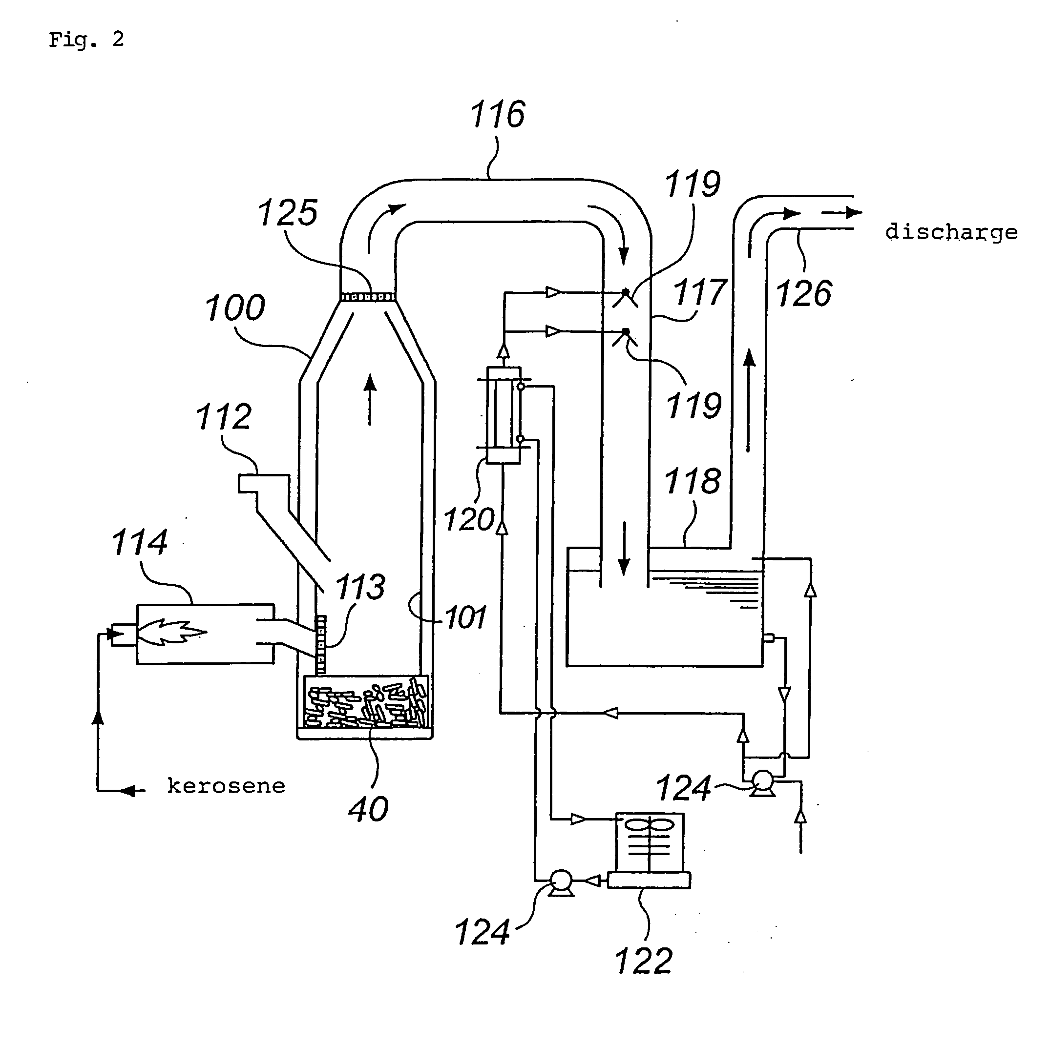
[0059] An automatic charging system of inflators into a thermally treating tower will be explained with reference to FIG. 1 and FIG. 2. FIG. 2 is a conceptual diagram of an inflator thermal treatment equipment including the automatic charging system of inflators into a thermally treating tower, which is shown in FIG. 1.

[0060] The automatic charging system of inflators into the thermally treating tower is constituted by combining the inflator conveying and discharging apparatus of Embodiment 1 and the inflator charging apparatus of Embodiment 2.

[0061] The upper end portion of the tubular passage 10 in the inflator conveying and discharging apparatus and an end portion of the first vertical passage 51 in the inflator charging apparatus are connected to be united as shown in FIG. 1.

[0062] An end portion of the second vertical passage 52 of the inflator charging apparatus is connected to an inflator charging port 112 as shown in FIG. 2.

[0063] The inflators 40 ...


PUM

PropertyMeasurementUnit
angleaaaaaaaaaa
timeaaaaaaaaaa
temperatureaaaaaaaaaa

Abstract

The present invention provides an automatic charging system of inflators into the thermally treating tower. The inflators 40 are conveyed inside a tubular passage 10 by a bucket 12 in an inflator conveying and discharging apparatus, and they are discharged into a first vertical passage 51 of an inflator charging apparatus. The inflators 40 are charged into a thermally treating tower 100 via a flat passage 53 and a second vertical passage 52.

Description

TECHNICAL FIELD WHERE THE INVENTION BELONGS [0001] The present invention relates to an inflator charging apparatus used when inflators for an air bag are charged into a thermally treating tower, and an automatic charging system of inflators into a thermally treating tower using the inflator charging apparatus. BACKGROUND ART [0002] Recently, since new cars equipped with an air bag(s) has increased, a great deal of inflators accommodating gas generating materials therein will hereafter are seen at scrapping of these cars equipped with air bags. Therefore, from the viewpoint of safety and effective utilization of resources, it is necessary to ignite the gas generating materials by thermal treatment safely to recover metals and the like therefrom. Under such circumstances, a recovery / treatment system for inflators for an air bag is being started. [0003] For treatment of inflators for an air bag, a method in which thermal treatment is conducted to inflators for an air bag inside a therm...

Claims


Application Information

Patent Timeline
Patent Type & Authority Applications(United States)
IPC IPC(8): B01J4/00B01J7/00B09B3/00B09B5/00B60R21/26B60R21/264C06B21/00F23G5/44F23G7/00
CPCB09B3/00B09B3/0083B09B5/00B60R21/2644F23G2900/7001F23G5/442F23G7/003F23G2205/16F23G2205/18C06B21/0091B09B3/40
Inventor AOYAMA, KEISHINAKAZAWA, YUJI
Owner DAICEL CHEM IND LTD
Why Eureka
Try Eureka