Facial osteodistraction device

Inactive Publication Date: 2005-01-27
OSTEOMED
View PDF31 Cites 10 Cited by
  • Summary
  • Abstract
  • Description
  • Claims
  • Application Information

AI Technical Summary

Benefits of technology

[0005] In accordance with teachings of the present invention, the disadvantages and problems associated with osteodistraction of the midface and maxilla have been substantia

Problems solved by technology

Such a condition may lead to difficulties in a patient's movement.
A small jaw may cause difficulties in chewing or breathing (e.g., obstructive sle

Method used


Image

  • Facial osteodistraction device
  • Facial osteodistraction device
  • Facial osteodistraction device

Examples


Embodiment Construction

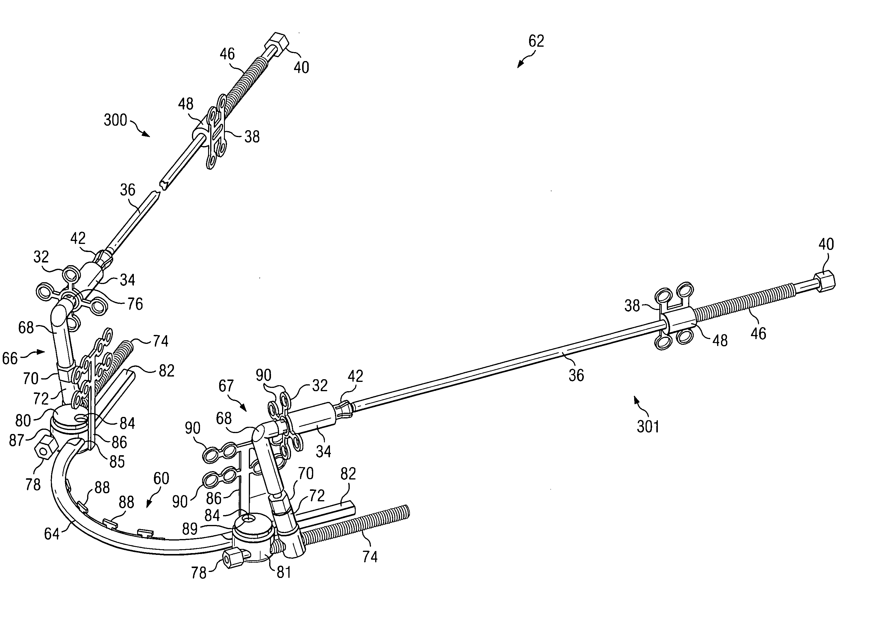
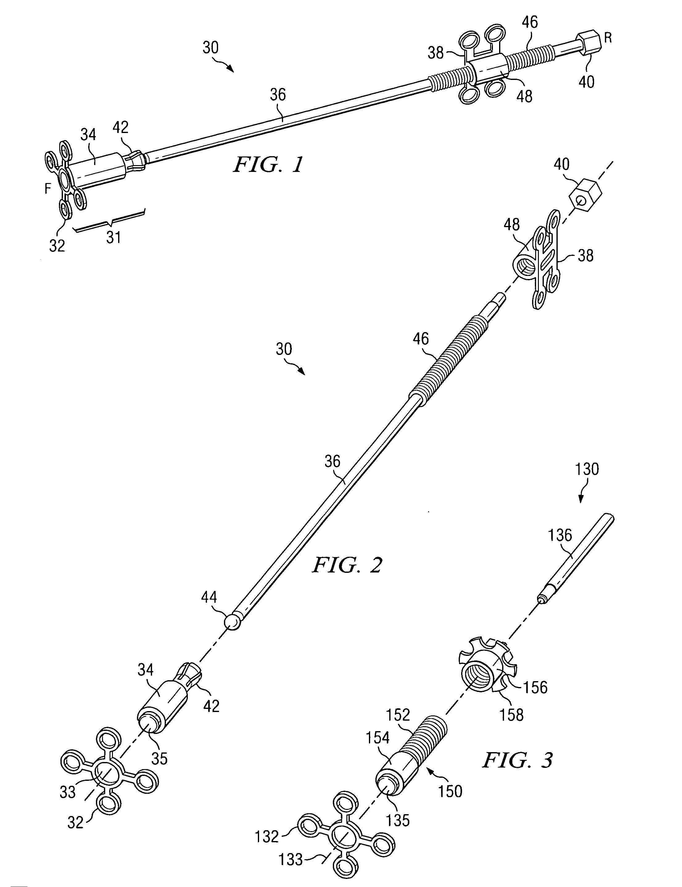
[0022]FIGS. 1 and 2 illustrate one embodiment of midface distraction device 30. Distraction devices such as midface distraction device 30 may be used to lengthen bones to correct congenital abnormalities and deformations following fractures or injuries. Osteodistraction is a procedure for lengthening bones by cutting a bone into two segments. The segments are drawn apart by a distraction device, such as midface distraction device 30. New bone grows in between the separated bone segments, eventually coupling the two segments together, resulting in a lengthened bone. As the bone grows in between the separated segments, the segments may be drawn apart further until the desired bone length is achieved. Once the desired bone length is achieved, the device may remain on the bone until the newly grown bone is sufficiently strong, and then be removed.

[0023] In a particular embodiment, midface distraction device 30 could be a Le Fort III distraction device. Le Fort III distraction devices m...


PUM


Abstract

A system for midface distraction including a left side distraction mechanism and a right side distraction mechanism, each including: an implantable anchor configured to be coupled to a bone of the malar region, an implantable anchor configured to be coupled to a bone of the cranium, and a distraction rod coupling the anchors. The system also includes a maxillary bridge configured to couple the left side distraction mechanism with the right side distraction mechanism and wherein couplings between the maxillary bridge and the right and left distraction mechanisms are configured to be internal to a patient.

Description

CROSS REFERENCE TO RELATED APPLICATIONS [0001] This application is a continuation-in-part of U.S. patent application Ser. No. 10 / 440,001 filed by Stephen A. Schendel on May 16, 2003, which is a continuation of U.S. patent application Ser. No. 09 / 988,529 filed by Stephen A. Schendel on Nov. 20, 2001, now U.S. Pat. No. 6,589,250.TECHNICAL FIELD OF THE INVENTION [0002] The present invention relates to a device for manipulation of facial bones, and more particularly, the invention relates to a device for distraction of the midface and maxilla. BACKGROUND OF THE INVENTION [0003] Bones sometimes develop at different rates, leaving some bones disproportionately shorter than other bones. Alternatively, injury may leave a bone shorter than its original length. Such a condition may lead to difficulties in a patient's movement. For instance, a patient with a shortened tibia may need special shoes for assistance in walking. A small jaw may cause difficulties in chewing or breathing (e.g., obstr...

Claims


Application Information

Patent Timeline
IPC IPC(8): A61B17/66
CPCA61B17/663
Inventor SCHENDEL, STEPHEN A.AHMAD, SHAHER A.THORNHILL, LISA REGINAMOCANU, VIOREL
Owner OSTEOMED
Why Eureka
Try Eureka