
Sternum suture wire with teardrop ring

a technology of suture wire and teardrop ring, which is applied in the field of suture wire for sternum closure material, can solve the problems of time and labor required for hemostasis, difficulty in passing a wire through the tiny hole, and possible bone fractures, so as to shorten the surgery time, avoid invasiveness, and avoid bone fracture.

Inactive Publication Date: 2005-01-27
KOSEKI TOMOAKI
View PDF10 Cites 168 Cited by
  • Summary
  • Abstract
  • Description
  • Claims
  • Application Information

AI Technical Summary

Benefits of technology

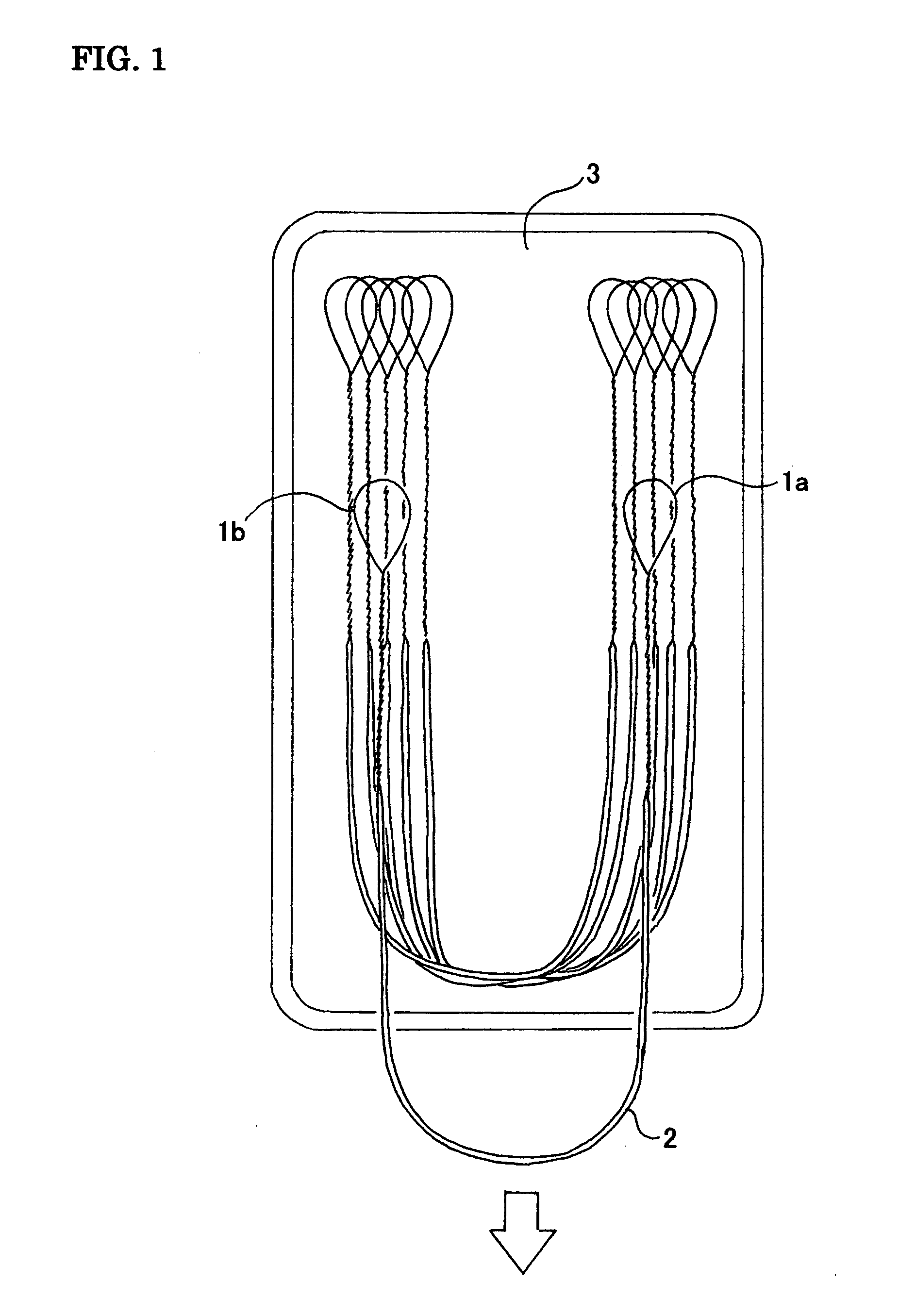
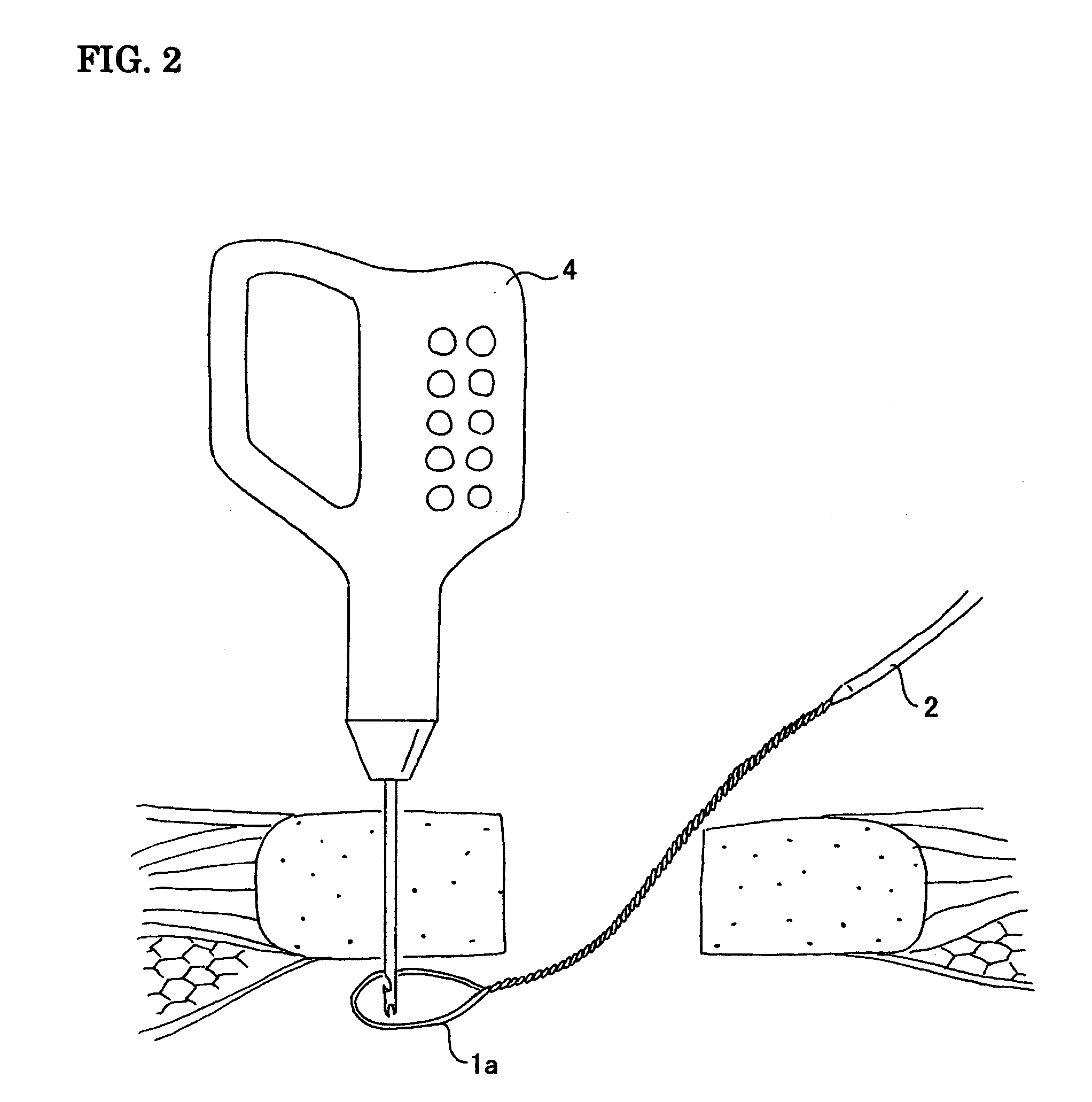
[0022] As explained above, with this invention, there is no invasiveness onto the sternum as when utilizing a wire with needle attached, and this invention enables piercing the wire through the sternum with easy operation of just placing the ring on the hook of the gimlet, shortening the surgery time. Taking out the wire from its container is easy, without any tangling, and a wire can be pulled out smoothly.

Problems solved by technology

When using the type wherein a needle is attached to one end of a wire has strong invasiveness onto the sternum, causing hemorrhage, and therefore time and labor is required for hemostasis.
In cases of surgeries on aged patients, bone fractures could occur due to bone fragility.
When using the type with gimlet to pierce the sternum, when a hole is made at the tip end of the gimlet, passing a wire through the tiny hole is difficult and the procedure takes time and labor.
When using a thread with a ring, as stated in document 3, when using a soft thread material, the procedure of placing the ring on the tip end of the gimlet that is pierced to the other side of the sternum is troublesome, and as this requires supporting of the ring part with a finger, there is a risk of harming the hand with the gimlet tip.
In a case of a metal wire, the ring part can be made into a relatively large ring in advance and approach from the foreside, but when the form is made in a true circle, a multiple number of wires tangle inside the container case, and it is difficult to take the wires out.

Method used


Image

  • Sternum suture wire with teardrop ring
  • Sternum suture wire with teardrop ring
  • Sternum suture wire with teardrop ring

Examples


Embodiment Construction

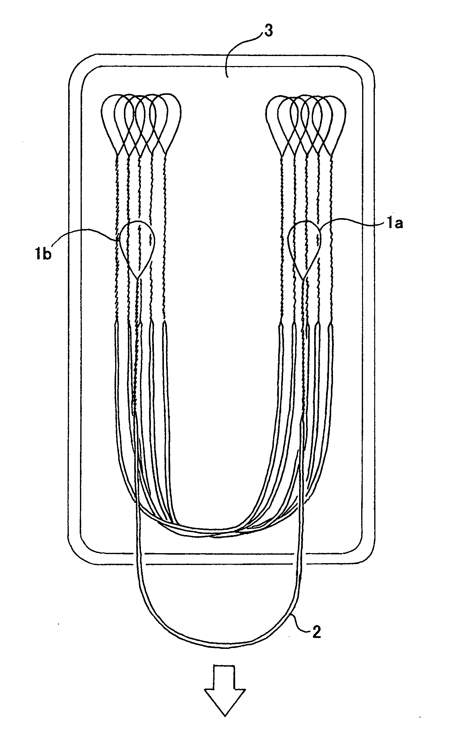
[0025] Hereafter, a description of the preferred embodiments of this invention is made in reference to drawings. FIG. 1 shows one embodiment of this invention, showing how a wire is taken out of its container. The material of the wire is SUS 316L, the center thick part of the wire has the diameter of 0.8 mm˜0.9 mm, the length being approximately 30 cm, and on the two ends of the wire, another wire is attached, made of material SUS316L, its outer diameter being 0.45 mm, the length being approximately 20 cm, twisted with the manufacturing method according to claim 2, the shape of the tip end being in teardrop shape ring 1a, 1b. In a cardiac surgery, five or six wires are usually used, and often five or six wires are set inside a container case 3. A typical procedure would be to first pull out the thick part of the wire 2 one by one. When the ring at both ends of the wire are in true circle, the rings tangle with each other, and when the rings are pulled out to the extracting direction...


PUM

PropertyMeasurementUnit
lengthaaaaaaaaaa
outer diameteraaaaaaaaaa

Abstract

A sternum suture wire with teardrop ring, wherein the center part of the wire is thick, both ends are made thin, and the two tip ends of the wire are shaped in teardrop rings. This invention provides a sternum suture wire which has least invasiveness onto the sternum, that can be passed through a sternum easily and speedily, and the wires do not tangle with each other inside the container case.

Description

CROSS-REFERENCE TO RELATED APPLICATIONS [0001] Not Applicable STATEMENT REGARDING FEDERALLY SPONSORED RESEARCH OR DEVELOPMENT [0002] Not Applicable INCORPORATION-BY-REFERENCE OF MATERIAL SUBMITTED ON A COMPACT DISC or REFERENCE TO A “MICROFICHE APPENDIX”[0003] Not Applicable BACKGROUND OF THE INVENTION [0004] (1) Field of the Invention [0005] This invention relates to a wire for sternum closure material used during a cardiac surgery. [0006] (2) Description of Related Art including information disclosed under 37 CFR 1.97 and 1.98. [0007] Material used for sternum suture can be categorized in two, one being sternum piercing needles attached to one end of a wire, and the other being wires with both ends to thin down, and the wire tip end is passed through a tip of a gimlet and pulled up after pierced through the sternum. The processing method making the two ends of the wire to thin down is already proposed in patent documents 1 and 2 and such. In patent document 3, there is a proposal ...

Claims


Application Information

Patent Timeline
Patent Type & Authority Applications(United States)
IPC IPC(8): A61B17/04A61B17/58A61B17/06A61B17/56A61B17/82
CPCA61B17/06133A61B2017/06042A61B17/823A61B17/06166
Inventor KOSEKI, TOMOAKI
Owner KOSEKI TOMOAKI
Learn More