Eureka AIR delivers breakthrough ideas for toughest innovation challenges, trusted by R&D personnel around the world.

Method for suturelessly attaching a biomaterial to an implantable bioprosthesis frame

Inactive Publication Date: 2005-01-27
PROVIDENCE HEALTH SYST OREGON
View PDF14 Cites 210 Cited by
  • Summary
  • Abstract
  • Description
  • Claims
  • Application Information

AI Technical Summary

Problems solved by technology

However, the use of such devices is often associated with thrombosis and other complications.
Suturing is a poor technique for joining multiple layers of biomaterial.
While suturing is adequate to join the biomaterial sheets to the metallic frame, the frame-sutured multiple sheets are not joined on their major surfaces and are therefore subject to leakage between the layers.
Suturing of the major surfaces of the biomaterial layers introduces holes into the major surfaces, increasing the risk of conduit fluid leaking through or a tear forming in one of the surfaces.
However, this approach is disadvantageous from manufacturing and implantation perspectives.
Suturing is time-consuming and labor-intensive.
As well, suturing entails repeatedly puncturing the biomaterial, creating numerous tiny holes that can weaken the biomaterial and potentially lead to leakage and infection after the graft device has been installed.
Moreover, the presence of suture material can enhance the foreign body response by the host patient, leading to a narrowing of the tubular vessel in which the graft is implanted.
Bioadhesives generally produce rigid, inflexible bond regions that can lead to local biomaterial tears and failure of the graft device.
In addition, some bioadhesives and photochemical cross-linking agents carry risk of acute and chronic toxicity and bio-incompatibility.

Method used


Image

  • Method for suturelessly attaching a biomaterial to an implantable bioprosthesis frame
  • Method for suturelessly attaching a biomaterial to an implantable bioprosthesis frame
  • Method for suturelessly attaching a biomaterial to an implantable bioprosthesis frame

Examples


Embodiment Construction

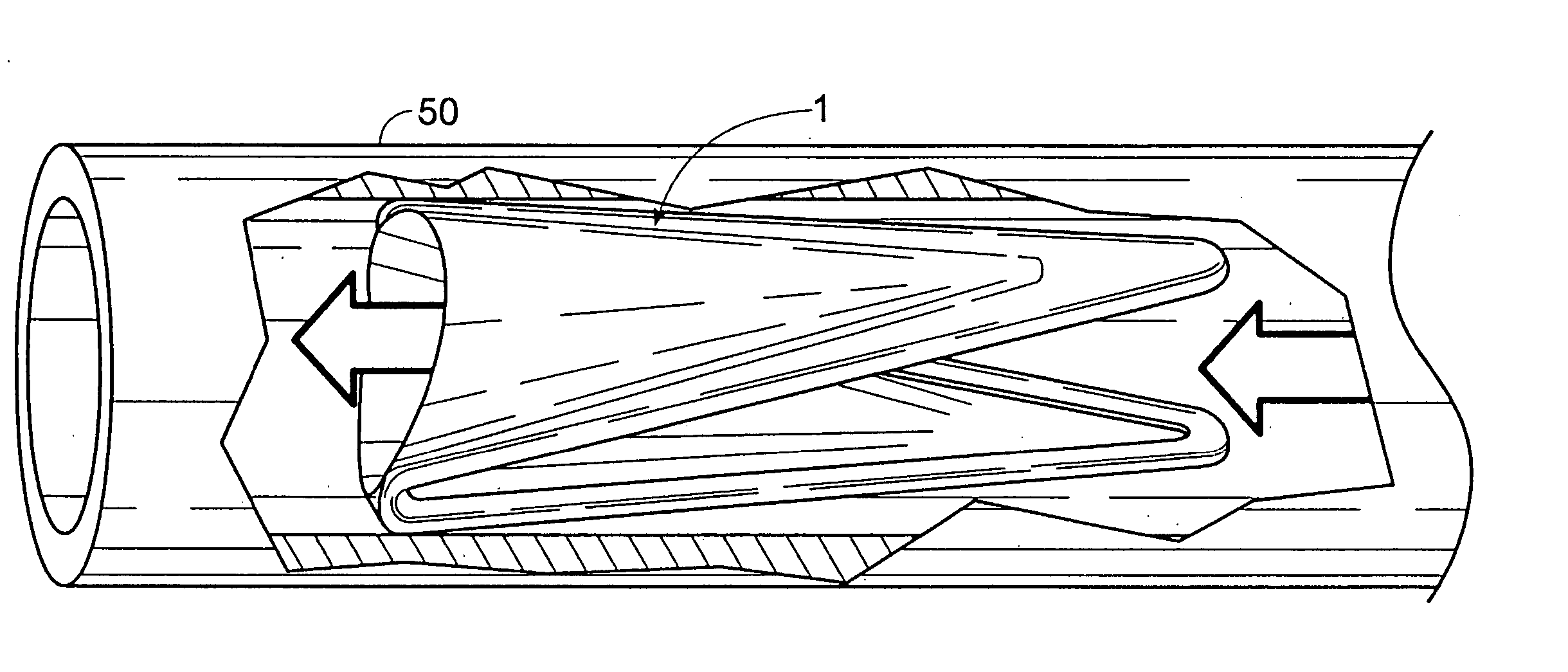
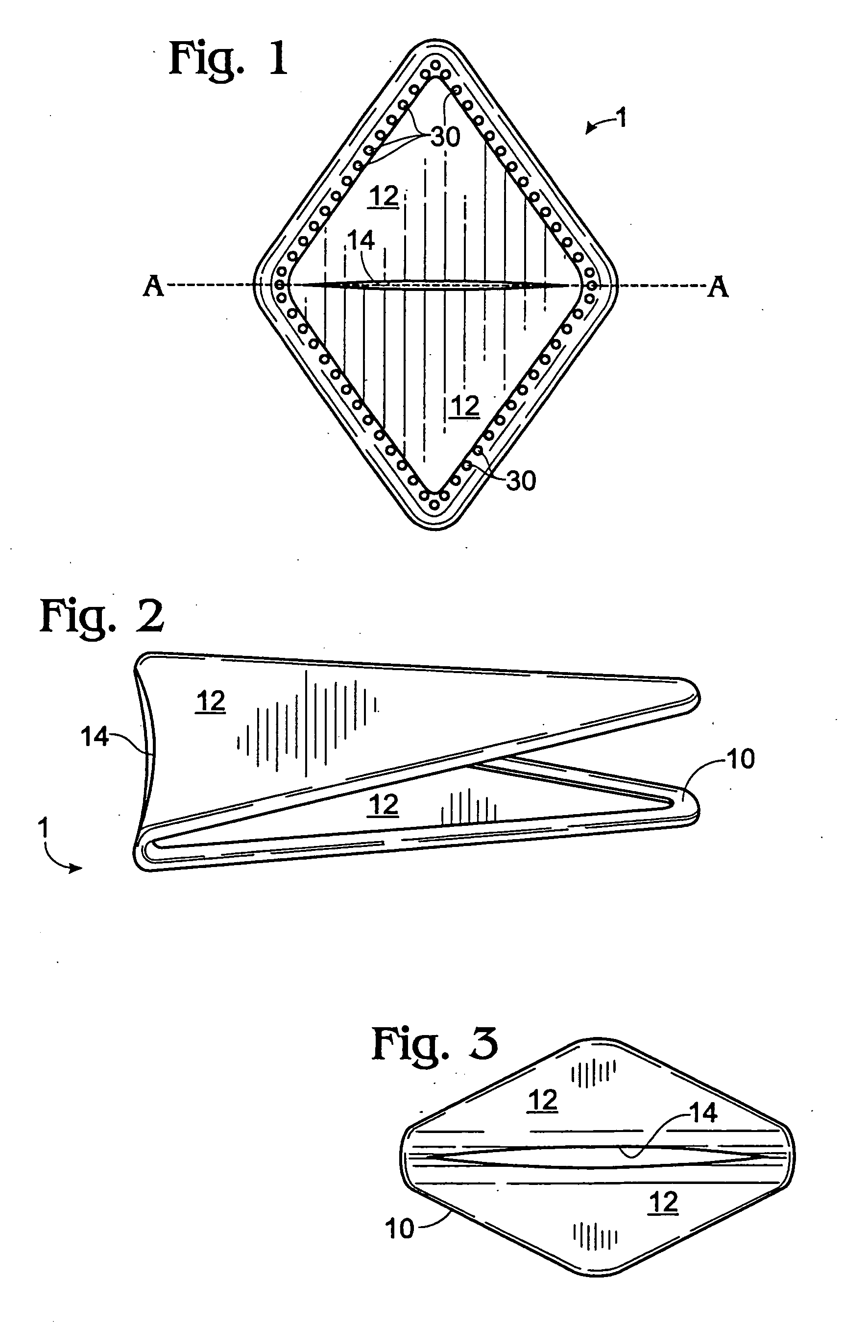
[0031] A valve graft 1 according to the present disclosure is shown in FIGS. 1-3. The valve graft generally comprises a valve frame 10 defining a valve frame open area (18 in FIG. 4). The open area is spanned by a pair of valve flaps 12 constructed of a biomaterial, discussed below. The valve flaps have positioned therebetween an aperture 14.

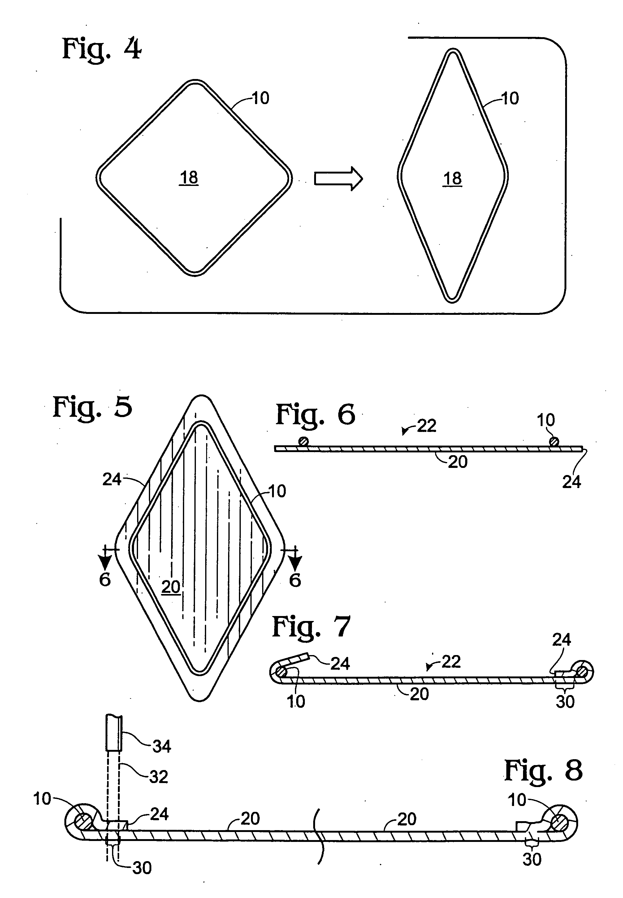
[0032] The valve frame 10 is preferably a closed loop and is commonly constructed of fine-gauge metal (e.g., 0.014 inch diameter), although other materials can be effectively employed. For example, the valve frame can alternatively be made of a synthetic material such as TEFLON (polytetrafluoroethylene). As well, the valve frame can be fabricated of a resorbable or biodegradable composition.

[0033] In one embodiment, the valve frame 10 is a memory wire formed into a desired shape. As illustrated herein, the valve frame is rhomboidal, although other shapes can be utilized to effect a variety of valve shapes and dimensions.

[0034] Such a shape me...


PUM


Abstract

A bioprosthetic valve graft comprises a valve frame and valve flaps, the latter acting to open or close a valve aperture to directionally control fluid flow through the bioprosthesis. The bioprosthetic valve graft comprises method for suturelessly attaching a biomaterial suturelessly bonded to the A method for securing a biomaterial to a valve frame includes positioning a flexible valve frame defining an open area on a first major surface of a biomaterial sheet having a peripheral edge, wherein positioning serves to approximate the valve frame and the peripheral edge of the biomaterial sheet to form an at least first bonding locus: and suturelessly bonding the biomaterial to the valve frame at the at least first bonding locus. The method avoids the disadvantages associated with conventional sutures and substantially reduces medical complications in implantations.

Description

RELATED APPLICATION DATA [0001] This application is a divisional of U.S. Ser. No. 10 / 104,499, filed on March 21, 2002.STATEMENT OF GOVERNMENT RIGHTS [0002] This invention was made with the U.S. Government support under Grant Number DAMD17-96-1-6006, awarded by the Army Medical Research and Materiel Command. The U.S. Government may have certain rights in the invention.BACKGROUND OF THE INVENTION [0003] The present disclosure is related to the field of artificial valves, and more specifically to an implantable, sutureless valve graft comprising a biomaterial. The disclosure is further related to a method for suturelessly bonding a biomaterial to a bioprosthetic frame. [0004] Prosthetic stents and valves have been described in the prior art. Stents have been used with success to overcome the problems of restenosis or re-narrowing of a vessel wall. Valves are exemplified by U.S. Pat. No. 5,258,023 (to Roger), in which a prosthetic valve is taught that is constructed of synthetic materia...

Claims


Application Information

Patent Timeline
IPC IPC(8): A61F2/06A61F2/24
CPCA61F2/2418A61F2230/0026A61F2220/0075A61F2/2475
Inventor XIE, HUABUCKLEY, LISA A.
Owner PROVIDENCE HEALTH SYST OREGON
Why Eureka
Eureka Blog
Learn More