
Vehicle test stand

a technology for test stands and vehicles, applied in the direction of instruments, force/torque/work measurement apparatus, vehicle tractive/propulsive power measurement, etc., can solve the problem of short set-up time required for the preparation of test, and achieve the effect of not having to pay a lot of structural expenditur

Inactive Publication Date: 2005-02-03
DURR ASSEMBLY PROD GMBH
View PDF7 Cites 30 Cited by
  • Summary
  • Abstract
  • Description
  • Claims
  • Application Information

AI Technical Summary

Benefits of technology

[0004] In contrast thereto, the object of the invention is to provide a vehicle test stand and a method with the aid of which the components in the drive train of a motor vehicle can be examined without heavy structural expenditure.

Problems solved by technology

Consequently, the set-up time required for the preparation of the test is very short.

Method used


Image

  • Vehicle test stand
  • Vehicle test stand
  • Vehicle test stand

Examples


Embodiment Construction

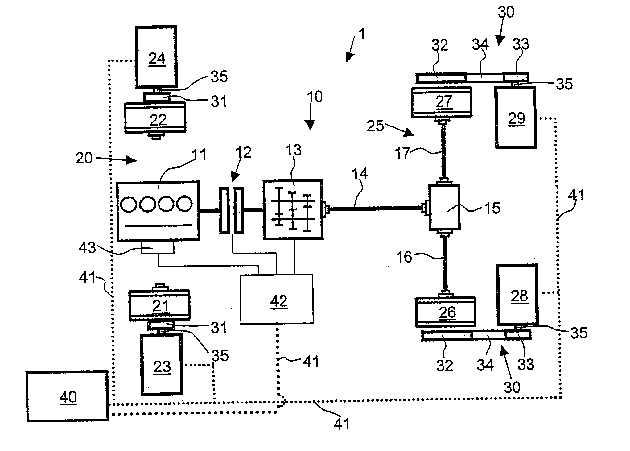
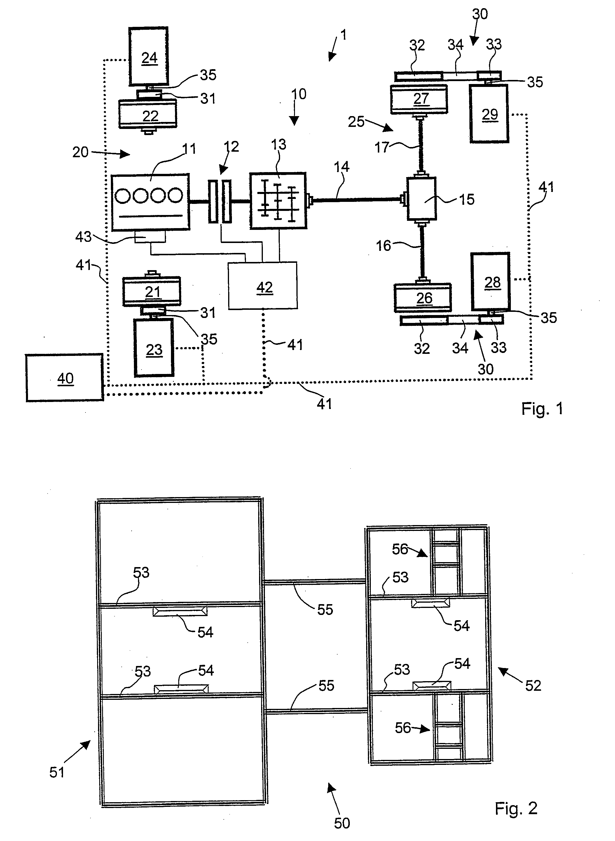
[0016] A vehicle test stand 1 in accordance with the invention is schematically illustrated in FIG. 1. A vehicle 10 is shown therein in abstracted form. The vehicle 10 comprises an internal combustion engine 11 which is connected to the input of a gear box 13 by a clutch 12. The output of the gear box 13 is connected via a drive shaft 14 to a rear axle differential 15 from which extend the lateral propeller shafts 16, 17 that drive the wheels 26, 27 on a driven rear axle 25 of the vehicle 10.

[0017] The vehicle 10 comprises two steerable vehicle wheels 21, 22 on the front axle 20. In the case of an all-wheel drive, these wheels can be connected by lateral propeller shafts to a front axle differential, the latter being connected to the gear box 13.

[0018] All four vehicle wheels 21, 22, 26, 27 are connected to loading machines 23, 24, 28, 29. The loading machines 23, 24, 28, 29 on the wheels 21, 22 of the front axle 20 are bolted directly to the rims of the wheels 21, 22 by means of ...


PUM


Abstract

The invention relates to a vehicle test stand including a device for fixing a motor vehicle on the test stand. A loading machine is adapted to be coupled to the drive train of the motor vehicle, whereby the loading machine can both drive and brake the drive train. In accordance with the invention, the loading machine is directly or indirectly connectable to a rim of a motor vehicle wheel in force-locking manner.

Description

FIELD OF THE INVENTION [0001] The present disclosure relates to the subject matter disclosed in German Patent Application No. 103 28 461.3 of Jun. 25, 2003, the entire specification of which is incorporated herein by reference. [0002] The invention relates to a vehicle test stand including the features indicated in the preamble of claim 1 as well as to a method of testing components in the drive train of a motor vehicle including the features indicated in claim 7. BACKGROUND OF THE INVENTION [0003] A test stand for testing the drive train of a vehicle is known from EP 0 338 373 A2. Therein, two mutually independent moment-regulated electrical loading machines are flanged directly onto the shafts in the drive train being tested. Rollers upon which the wheels of the vehicle are adapted to roll are not used here. A simulation of the rolling resistances, the wheels and the behaviour of the vehicle under acceleration exclusively of the vehicle components present in the form of real parts...

Claims


Application Information

Patent Timeline
IPC IPC(8): G01M13/02G01M17/007
CPCG01M17/007G01M13/025
Inventor TENTRUP, THOMASSCHENK, JANGEHRING, OTTMARHEILMANN, HARROSCHWARZHAUPT, ANDREASSPIEGELBERG, GERNOTSTAHL, WOLFGANGSULZMANN, ARMIN
Owner DURR ASSEMBLY PROD GMBH
Learn More