
Spring standoff for a reciprocating device

a technology of reciprocating device and standoff, which is applied in the direction of reciprocating piston engine, positive displacement engine, hot gas positive displacement engine plant, etc., can solve the problems of unable to use a liquid component lubricant, and reducing the accuracy of the centering process, so as to achieve convenient and easy centering operation

Inactive Publication Date: 2005-02-03
LG ELECTRONICS INC +1
View PDF2 Cites 4 Cited by
  • Summary
  • Abstract
  • Description
  • Claims
  • Application Information

AI Technical Summary

Benefits of technology

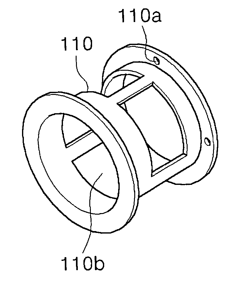
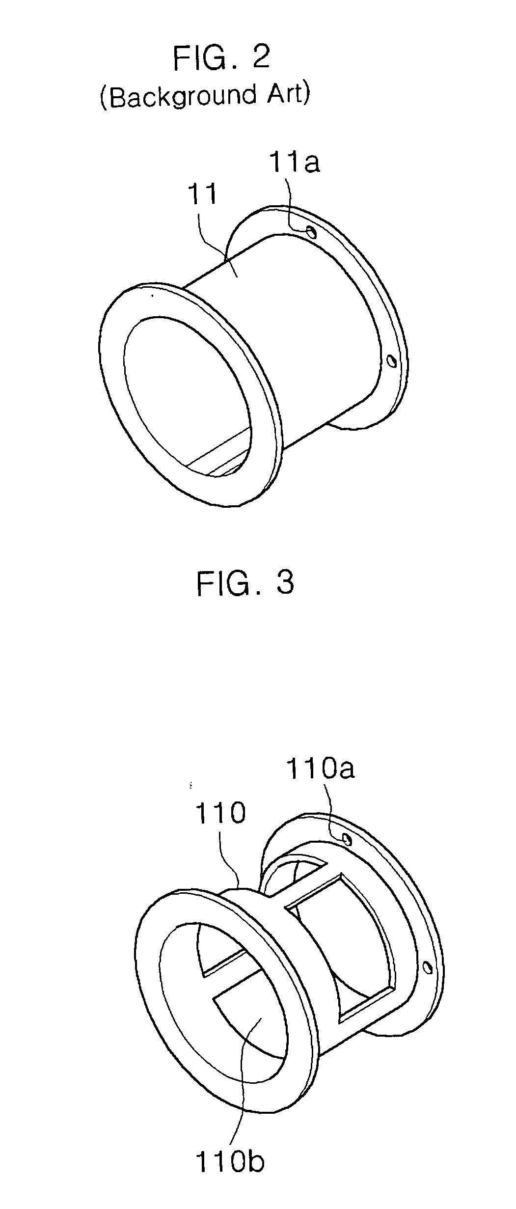
[0019] It is a benefit of the invention to provide a reciprocating device to which a spring standoff having an open wall portion is provided, thereby improving the efficiency of the centering process.
[0027] According to the structure of the cooler according to the present invention, and the centering process of the displacer in the cooler, the centering operation can be performed more conveniently and easily.

Problems solved by technology

A reciprocating device in the form of a cooler may perform cryogenic refrigeration, and therefore cannot use a lubricant having a liquid component.
The frictionally contacting portion is thus worn away with use, resulting in the fracture and failure of the product.
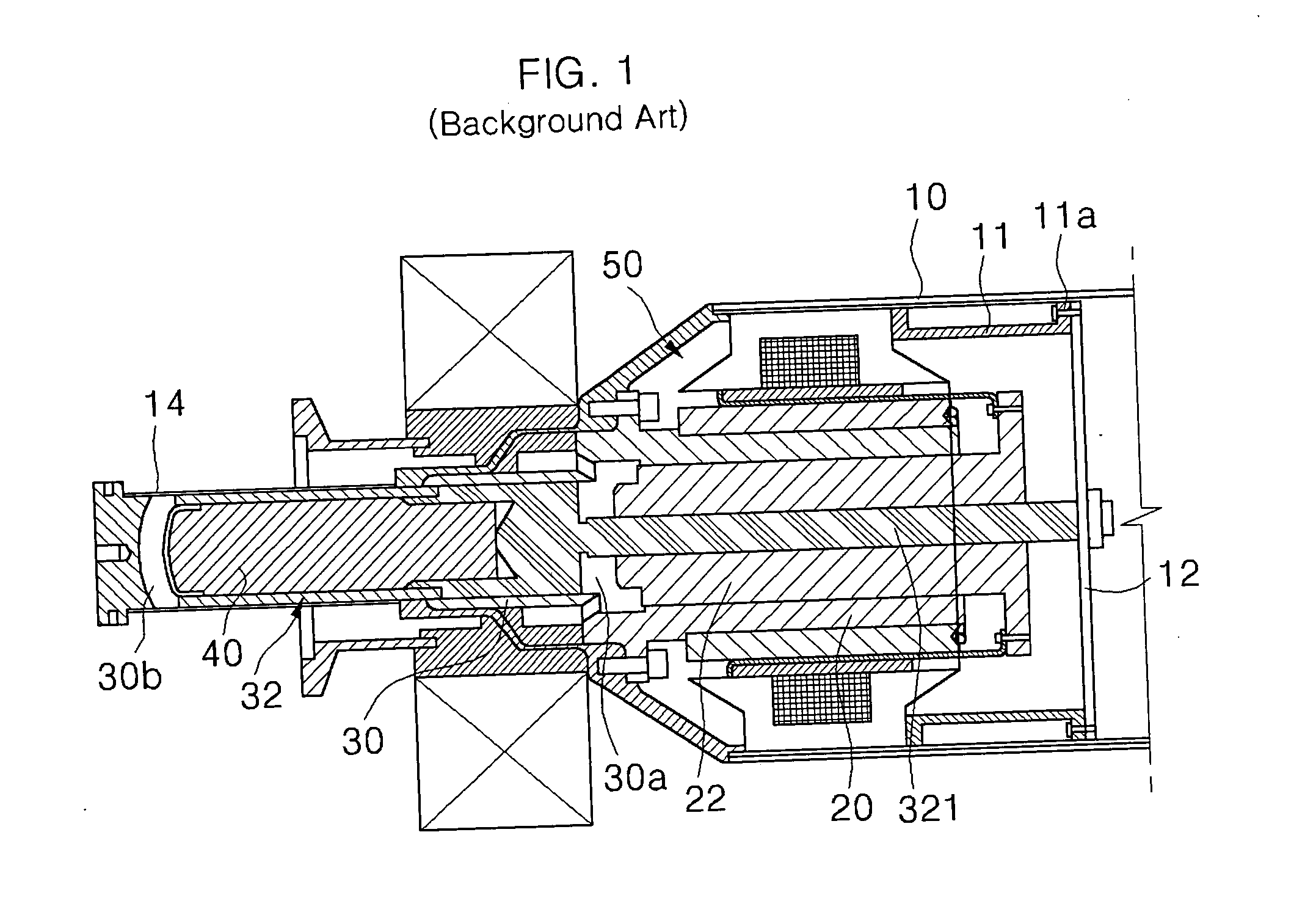
Thus, a jig (known in the art) performing a centering operation must move a considerable amount, since the end of the displacer rod is located a considerable distance from the “origin” from which the “moment arm” (displacer rod 321) extends, thereby potentially reducing the accuracy of the centering process.
Additionally, since the displacer rod 321 often protrudes beyond the spring 12 by only a small amount, it is often difficult to apply the jig.
As a result, since the freedom movement of the displacer rod 321 is very low, it is difficult to efficiently align the concentric positioning of the reciprocating parts.

Method used


Image

  • Spring standoff for a reciprocating device
  • Spring standoff for a reciprocating device
  • Spring standoff for a reciprocating device

Examples


Embodiment Construction

[0033] The particulars shown herein are by way of example and for purposes of illustrative discussion of the embodiments of the present invention only and are presented in the cause of providing what is believed to be the most useful and readily understood description of the principles and conceptual aspects of the present invention. In this regard, no attempt is made to show structural details of the present invention in more detail than is necessary for the fundamental understanding of the present invention, the description taken with the drawings making apparent to those skilled in the art how the several forms of the present invention may be embodied in practice. For example, it is readily appreciable by those skilled in the art that the present invention is applicable to a wide variety of reciprocating or oscillating devices and mechanisms.

[0034] A reciprocating device of the present invention has a configuration in which a spring standoff is connected to a planar spring. The ...


PUM


Abstract

A spring standoff for a reciprocating device, the standoff having a generally cylindrical body and having a window in a circumferential surface of the body, and a flange at each end of the body, one flange to be coupled to a planar spring of the reciprocating device, and the other flange to be coupled to a sealing container of the reciprocating device. The body generally concentrically houses at least a portion of a reciprocating rod coupled to the planar spring of the reciprocating device.

Description

CROSS-REFERENCE TO RELATED APPLICATION [0001] The present application is related to Korean Patent Application No. 2002-006327, filed on Feb. 4, 2002, the disclosure of which is expressly incorporated by reference in its entirety. BACKGROUND OF THE INVENTION [0002] 1. Field of the Invention [0003] The present invention relates to a spring fixing or securing part, and more particularly, to a spring standoff having an open central portion for improving the efficiency of the centering operation of a reciprocating rod displacer during an assembly process. [0004] 2. Description of the Related Art [0005] Generally, a variety of reciprocating devices, including but not limited to free-piston machines, are often used in a heat regeneration type of refrigerator, including but not limited to Stirling coolers, Gifford-McMahon refrigerators, and the like. [0006] A conventional free-piston machine is described in U.S. Pat. No. 6,293,184, which issued to Unger on Sep. 25, 2001, the contents of whi...

Claims


Application Information

Patent Timeline
Patent Type & Authority Applications(United States)
IPC IPC(8): F01B11/00
CPCF01B11/00
Inventor WISEMAN, ROBERT B.UNGER, REUVENWEEKS, DAVIDLARGENT, FLOYDCHUNG, WOO SUK
Owner LG ELECTRONICS INC
Learn More