Heat sink element coupling structure

a technology of heat sink elements and coupling structures, which is applied in the direction of basic electric elements, semiconductor devices, lighting and heating apparatus, etc., can solve the problems of serious limitations in profile variety and performance range, and cannot be conjoined to the heat sink mounting plate, and achieves the effect of easy loosing nor shifting during assembly

Inactive Publication Date: 2005-02-03
CHENG TUNG CHEN +1
View PDF17 Cites 18 Cited by
  • Summary
  • Abstract
  • Description
  • Claims
  • Application Information

AI Technical Summary

Benefits of technology

[0005] The objective of the invention herein is to provide an improved heat sink element coupling structure capable of total mechanical engagement

Problems solved by technology

If the coupling structure is only disposed on the lower lateral edge of every individual heat sink element plate, but not on the upper lateral edge, they cannot be conjoined to the heat sink mounting plate.
Since the coupling structure of conventional head sink must be situated on the upper and lower edge of each single heat sink element plate, only rectangular shaped heat sinks can b

Method used


Image

  • Heat sink element coupling structure
  • Heat sink element coupling structure
  • Heat sink element coupling structure

Examples


Embodiment Construction

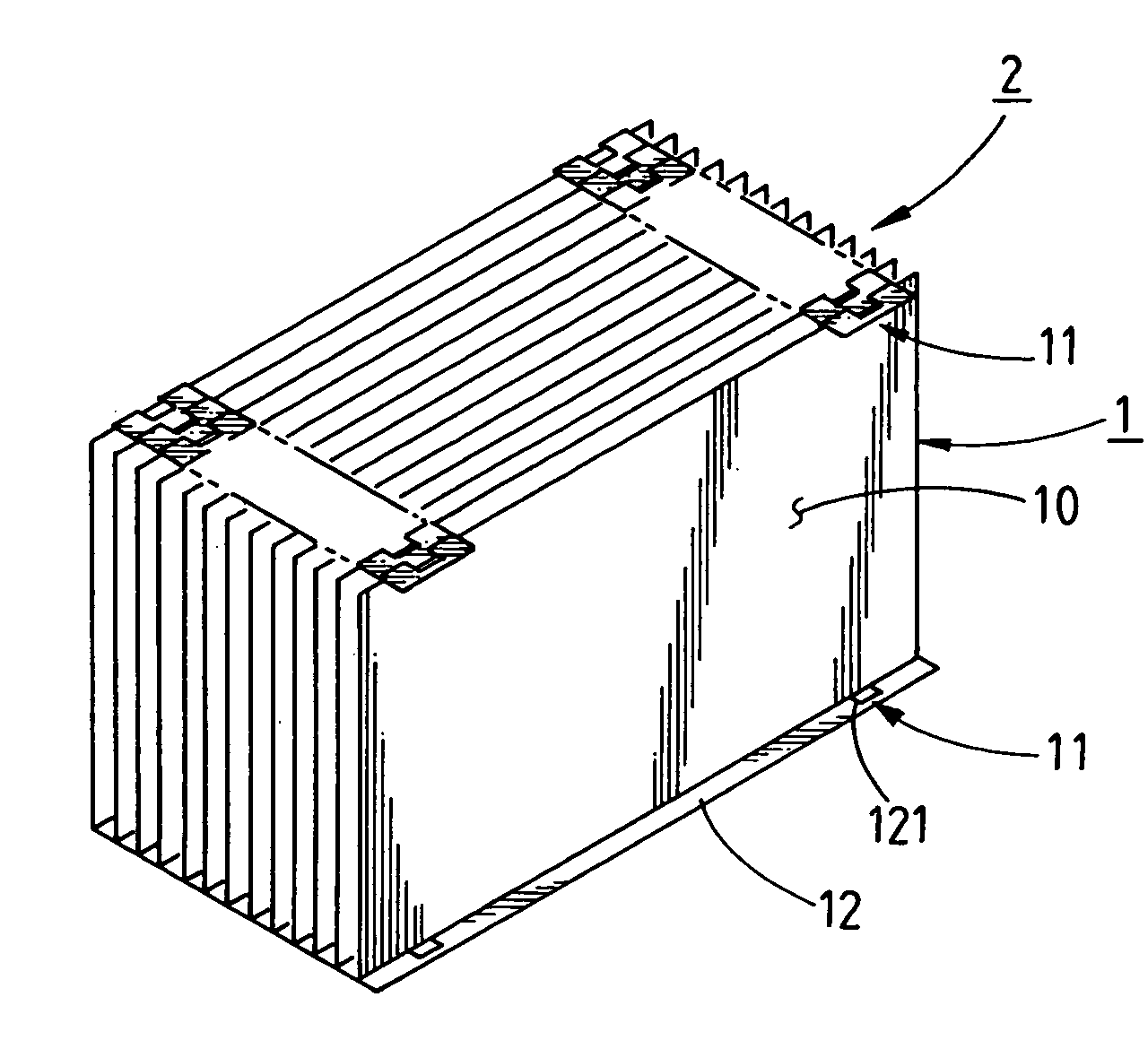
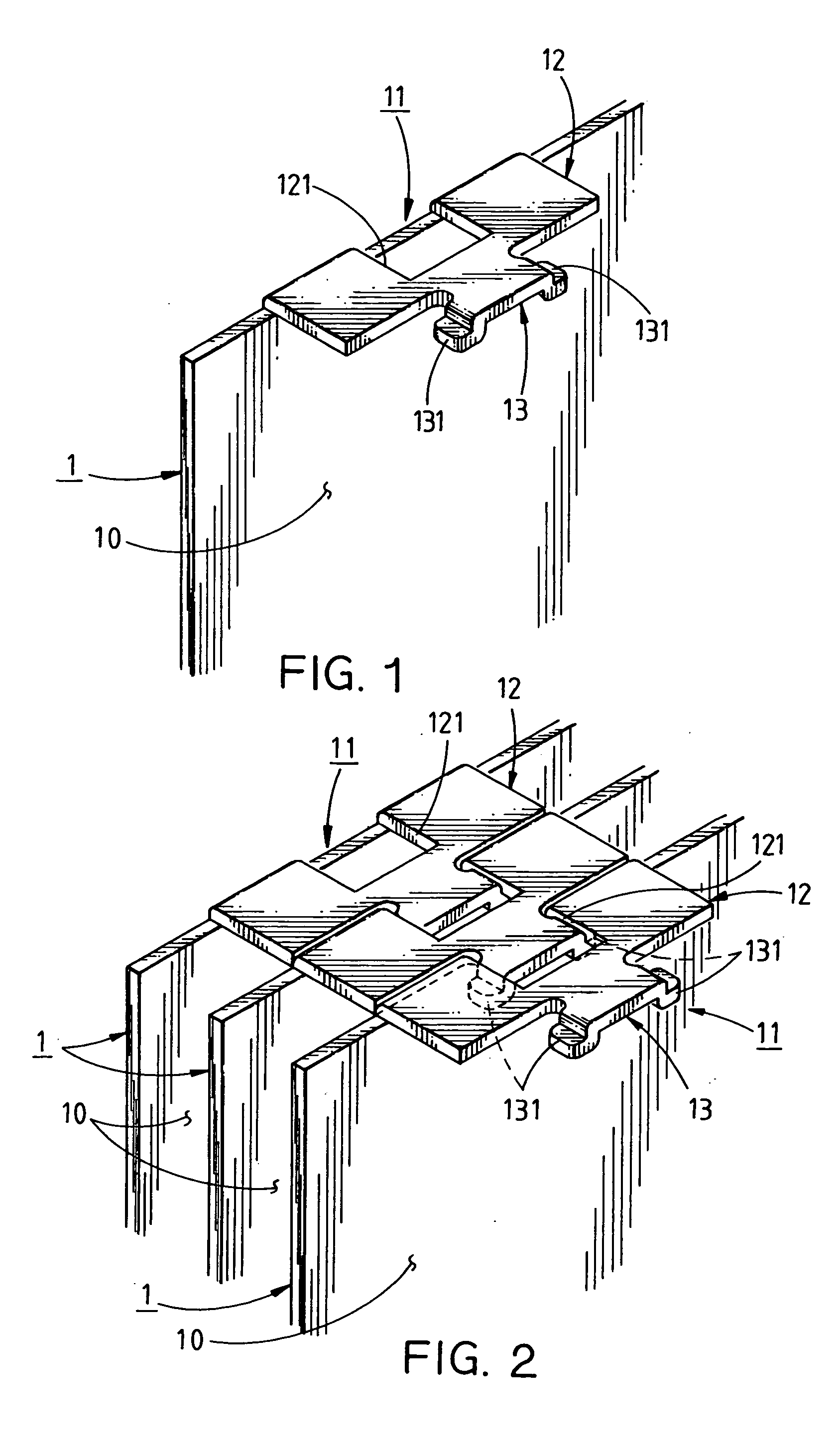
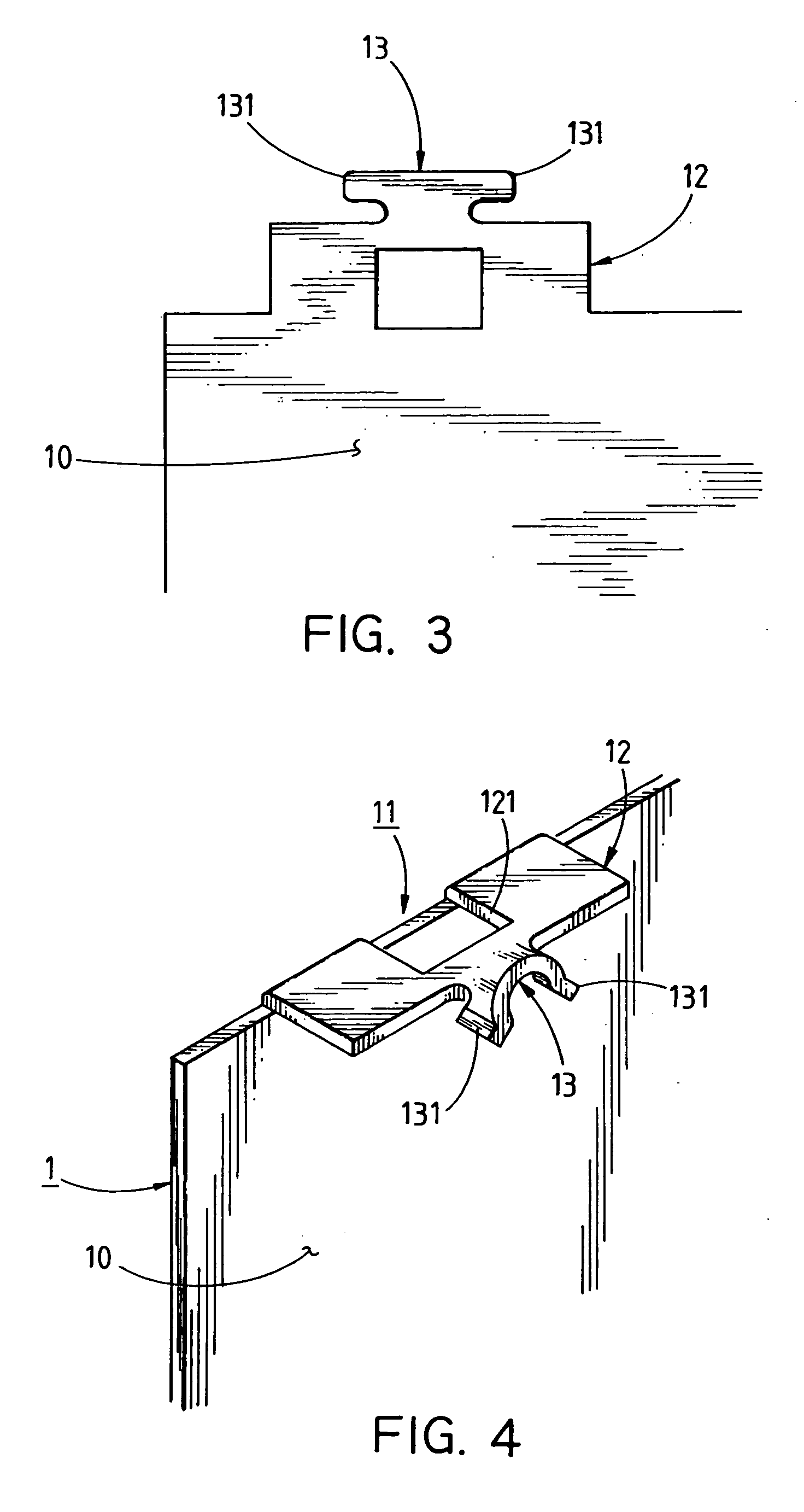
[0019] Referring to FIG. 1, the isometric drawing of the invention herein, the drawing depicts a coupling structure 11 at the left corner section on the upper edge of a single heat sink element 1 plate 10 that is symmetrically or correspondingly disposed on the coupling structure 11 at the right side of the lower edge or the left or right side of the lower edge of the said single heat sink element 1 plate 10. The said coupling structure 11 is comprised of a minimum of one or more folded appendages 12 of appropriate length that are formed by bending along the upper or lower edge, the middle, or other suitable position of the single heat sink element 1 plate 10; an opening 121 disposed at the confluence of the said folded appendage 12 and the said single heat sink element 1 plate 10 that penetrates the said folded appendage 12 to form a perforated construct; and a linking member 13 that extends outward from the said folded appendage 12 and, furthermore, is positioned at the distal ext...


PUM


Abstract

An improved heat sink element coupling structure comprised of a minimum of one or more folded appendages that are formed by bending along the upper or lower lateral edges, the middle, or other suitable position of a single heat sink element or along the two sides of one lateral edge or middle position of a single heat sink element; an opening disposed at the confluence of the folded appendage and the single heat sink element plate that penetrates the folded appendage to form a perforated construct; and a linking member that extends outward from the folded appendage and, furthermore, is positioned at the distal extremity of the single heat sink element plate. The features of the present invention include the following innovations. The linking member also has two lock tabs along its two sides that extend from the two sides at the leading extremity of the linking member. During interconnection, the lock tabs along the two sides of the linking member on single heat sink elements are articulated into an O shape and engaged into the opening of another immediately adjacent single heat sink element. Furthermore, the linking member and the two lock tabs at its two sides are formed into a horizontal S shape or an inverted horizontal S-shaped arrangement such that they are crimped onto the other single heat sink element plate and also firmly secured against the two lateral edges of the opening to prevent unintentional dislodging.

Description

BACKGROUND OF THE INVENTION [0001] 1) Field of the Invention [0002] The invention herein relates to heat dissipation fixtures, specifically an improved heat sink element coupling structure capable of total mechanical engagement that cannot be unintentionally dislodged, the coupling structure of which is disposed on a single side of each heat sink element to interconnect a plurality thereof into a heat sink. [0003] 2) Description of the Prior Art [0004] In conventional “assembly-type” heat sinks, such as those disclosed in patent application No. 407753, 460110, 468931, 484704, and 516794 in the Taiwan Patent Bulletin, the coupling structure for achieving interconnection consists of a “stack fit” approach. As a result, a coupling structure must be disposed at the upper and lower edge of each individual heat sink element plate so they can be interconnected into a heat sink. If the coupling structure is only disposed on the lower lateral edge of every individual heat sink element plate,...

Claims


Application Information

Patent Timeline
IPC IPC(8): F28F3/02H01L23/367
CPCF28F3/02H01L23/3672H01L2924/0002H01L2924/00
Inventor CHENG-TUNG, CHENJIAN-FA, YEH
Owner CHENG TUNG CHEN
Why Eureka
Try Eureka