This helps you quickly interpret patents by identifying the three key elements:
Problems solved by technology
Method used
Benefits of technology
Benefits of technology
[0007] The present invention is made in view of the foregoing matters, and it is an object of the present invention to provide a vehicle front end structure, capable of improving cooling efficiency of auxiliary devices and reducing damage to the auxiliary devices and heat exchangers when a vehicle collides at a front side.
[0008] It is another object of the present invention to provide a vehicle front end structure having an improved designing flexibility around an engine hood.
[0009] It is further another object of the present invention to provide a vehicle front end structure in which heat radiating performance of heat exchangers is maintained even within a limited arrangement space.
Problems solved by technology
Therefore, it is difficult to effectively cool the auxiliary devices.
Method used
Image
Click on the blue label to locate the original text in one second.
Reading with bidirectional positioning of images and text.
Examples
first embodiment
[0041] (First Embodiment)
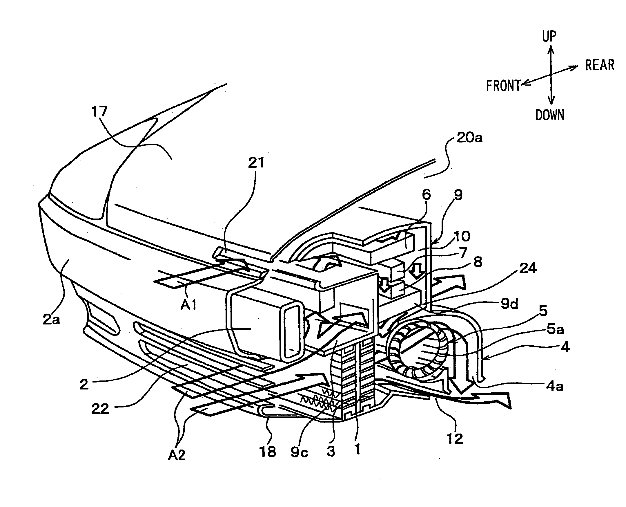
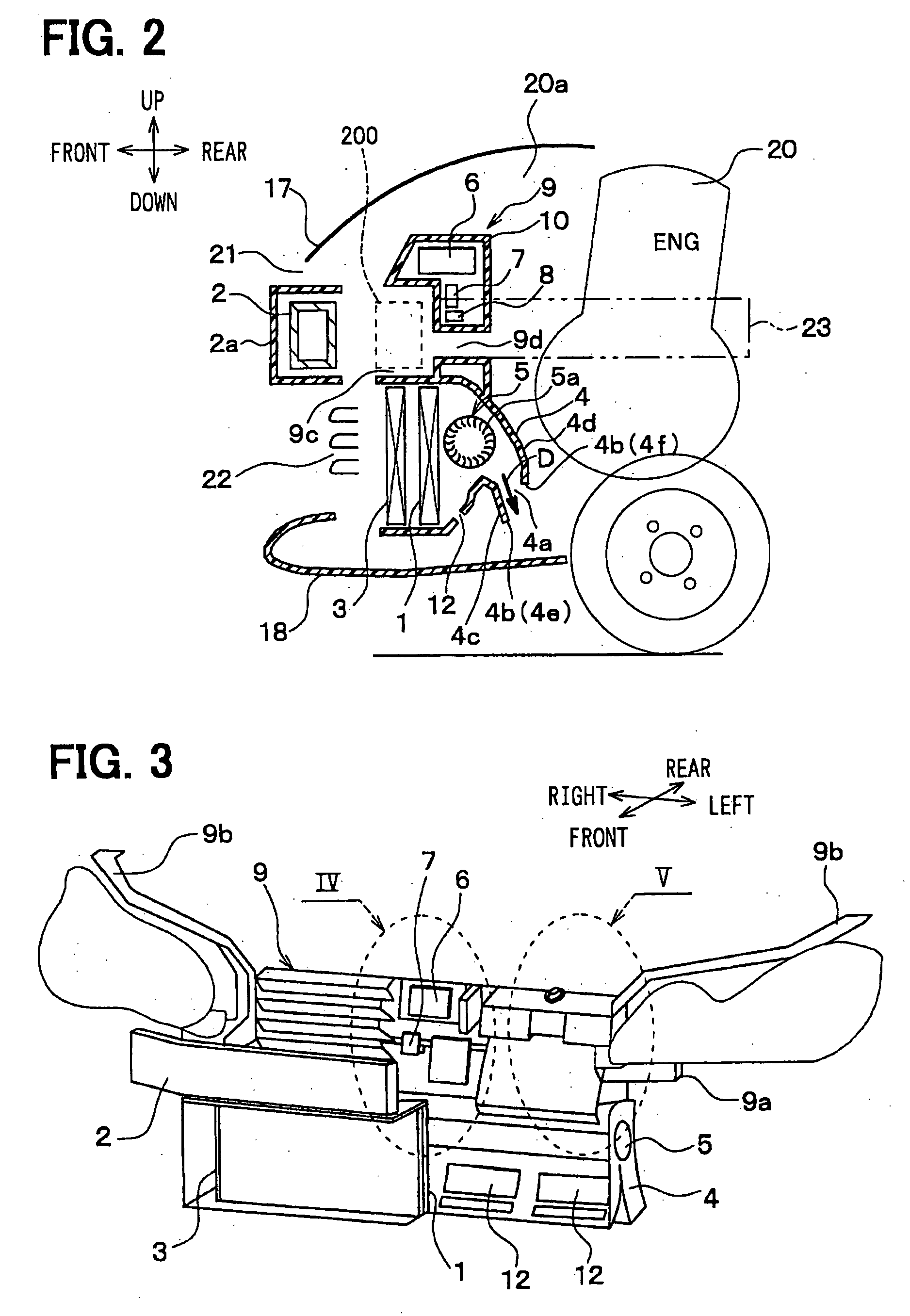
[0042]FIGS. 1 and 2 show a front end structure of a vehicle of the embodiment. FIG. 3 shows a schematic perspective view of a front end module in which a front end panel 9, heat exchangers 1, 3 for radiating heat and vehicle auxiliary devices are integrated, when viewed from a front side. In FIGS. 1 to 3, a front and rear arrow, an up and down arrow and a left and right arrow denote arrangement directions in the front end structure with respect to the vehicle.
[0043] Referring to FIGS. 1 to 5, the heat exchanger 1 is a radiator performing heat exchange between air (outside air) and an engine cooling water, thereby to cool the engine cooling water. The engine cooling water cools an engine (internal combustion engine) 20, which produces a driving power source of the vehicle.
[0044] In the embodiment, the radiator 1 has a width with respect to a vehicle left and right direction (width direction) larger than a height with respect to an up and down direction. Tha...
second embodiment
[0088] (Second Embodiment)
[0089] In the second embodiment, an axial flow fan 5b is used in place of the transverse fan 5a of the first embodiment, as shown in FIG. 6. Also in this case, advantages similar to the first embodiment are provided.
third embodiment
[0090] (Third Embodiment)
[0091] In the first and second embodiments, the radiator 1 and the condenser 3 are arranged completely lower than the bumper reinforcement member 2. In the third embodiment, as shown in FIG. 7, the radiator 1 and the condenser 3 are arranged at a position lower than the top wall 2b of the bumper reinforcement member 2. Furthermore, the radiator 1 and the condenser 3 are inclined such that the top ends are located more to the rear side of the vehicle than the bottom ends, with respect to the vehicle front and rear direction. As shown in FIG. 7, core surfaces 1a, 3a of the radiator 1 and the condenser 3 define an angle of inclination θ1 with, respect to a vertical direction.
[0092] In the third embodiment, the upper portions of the radiator 1 and the condenser 3 are partly located behind the bumper reinforcement member 2. However, since the radiator 1 and the condenser 3 are arranged in the inclined position toward the rear side, the heat radiating performance...
PUM
Abstract
In a front end structure of a vehicle, a heat exchanger is arranged at a position lower than a bumper reinforcement member, so a position of an engine hood is lowered. Electric auxiliary devices such as a radar, electronic control units for lights, and an air cleaner are arranged at a position higher than the bumper reinforcement member or at the rear of the bumper reinforcement member. By this arrangement, the electric auxiliary devices are arranged at a position which is less likely to be affected by the bumper reinforcement member in a case of light frontal crush.
Description
CROSS REFERENCE TO RELATED APPLICATION [0001] This application is based on Japanese Patent Applications No. 2003-279175 filed on July 0.24, 2003 and No. 2004-70610 filed on March 12, 2004, the disclosure of which are incorporated herein by reference. FIELD OF THE INVENTION [0002] The present invention relates to a vehicle front end structure including heat exchangers, a bumper reinforcement member and the like. BACKGROUND OF THE INVENTION [0003] As shown in FIG. 16, a bumper reinforcement member 2 is generally provided at the front end of a vehicle at a predetermined height. The bumper reinforcement member 2 is in a form of beam and extends in a vehicle left and right direction. Heat exchangers 1, 3, such as a radiator and a condenser, are provided at the rear of the bumper reinforcement member 2. Further, air intake openings 21, 22 are formed above and under the bumper reinforcement member 2 to introduce cooling air toward upper side and lower side of core portions of the heat exch...
Claims
Application Information
Patent Timeline
Application Date:The date an application was filed.
Publication Date:The date a patent or application was officially published.
First Publication Date:The earliest publication date of a patent with the same application number.
Issue Date:Publication date of the patent grant document.
PCT Entry Date:The Entry date of PCT National Phase.
Estimated Expiry Date:The statutory expiry date of a patent right according to the Patent Law, and it is the longest term of protection that the patent right can achieve without the termination of the patent right due to other reasons(Term extension factor has been taken into account ).
Invalid Date:Actual expiry date is based on effective date or publication date of legal transaction data of invalid patent.

