Fault monitoring apparatus and method

a fault monitoring and fault technology, applied in the direction of instruments, emergency protective arrangements for automatic disconnection, electrical component structural associations, etc., can solve the problems of internal faults, internal arcing faults, internal faults,

Inactive Publication Date: 2005-02-03
CUK NIKOLA
View PDF21 Cites 39 Cited by
  • Summary
  • Abstract
  • Description
  • Claims
  • Application Information

AI Technical Summary

Benefits of technology

[0007] In accordance with one aspect of the invention, there is provided a fault condition monitoring apparatus for use with a fuse cutout. The apparatus includes a housing operable to be supported by the fuse cutout, the housing having first and second contacts operable to make electrical contact with fuse contacts on the fuse cutout when the housing is supported by the fuse cutout. The apparatus further includes a current sensor inside the housing and connected to the first and second contacts and includes a signaling device coupled to the current sensor and operable to cause a signal to be produced when current sensed by the current sensor meets a criterion.

Problems solved by technology

Power distribution transformers in a high voltage power distribution system are susceptible to internal and external faults.
Internal faults may occur due to gradual degradation and / or sudden breakdown of insulating properties of internal structures of the transformer resulting from thermal, electrical and mechanical stresses.
The loss of insulating properties of internal structures can lead to a short circuit within the transformer, creating an internal arcing fault.
A short circuit of this type usually causes burning of the winding, ultimately resulting in an open circuit in the primary winding, whether the fault was initiated in the primary or secondary winding.
When such a fault occurs, a fuse, normally installed in series between the high voltage line and the transformer, blows, interrupting current flow to the transformer.
Attempts to re-energize the transformer by replacing the fuse can result in further arcing within the transformer and this can rapidly increase the pressure inside the transformer to the point of explosion where burning oil and shards of th transformer casing may be rapidly expelled at the risk of injuring persons and property nearby.
External faults may occur due to insulation failures in a secondary circuit connected to the secondary winding of the transformer.
Re-energizing a transformer having a fault in the secondary circuit do s not normally cause an increase in pressure inside the transformer sufficient to create an explosive threat.
Internal faults are thus normally more dangerous than xternal faults.

Method used


Image

  • Fault monitoring apparatus and method
  • Fault monitoring apparatus and method
  • Fault monitoring apparatus and method

Examples


first embodiment

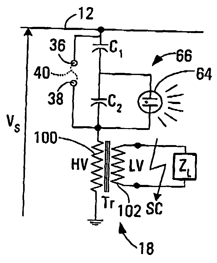
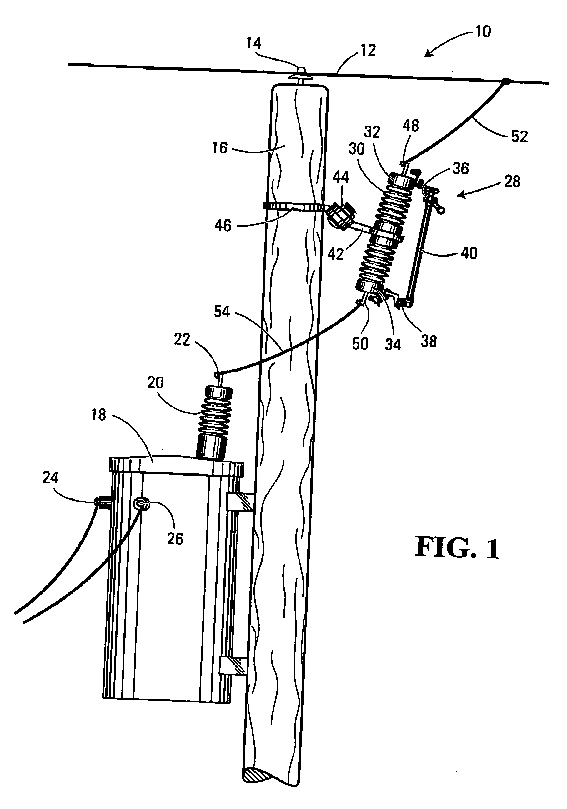
[0039] Referring to FIG. 1, a high voltage power distribution system incorporating an apparatus according to the invention is shown generally at 10. The system includes a high voltage line 12 carrying current associated with a single phase of a three phase power distribution system. The high voltage line 12 may carry a voltage of approximately 4 to 25 kV, for example. The high voltage line 12 is supported by an insulator 14 secured to a conventional power pole 16. To the power pole 16 is mounted a single-phase transformer 18 having a primary terminal bushing 20 having a primary terminal 22 connected to a primary winding (not shown) of the transformer. The transformer 18 also has secondary terminals 24 and 26, respectively, connected to a secondary winding (not shown) of the transformer.

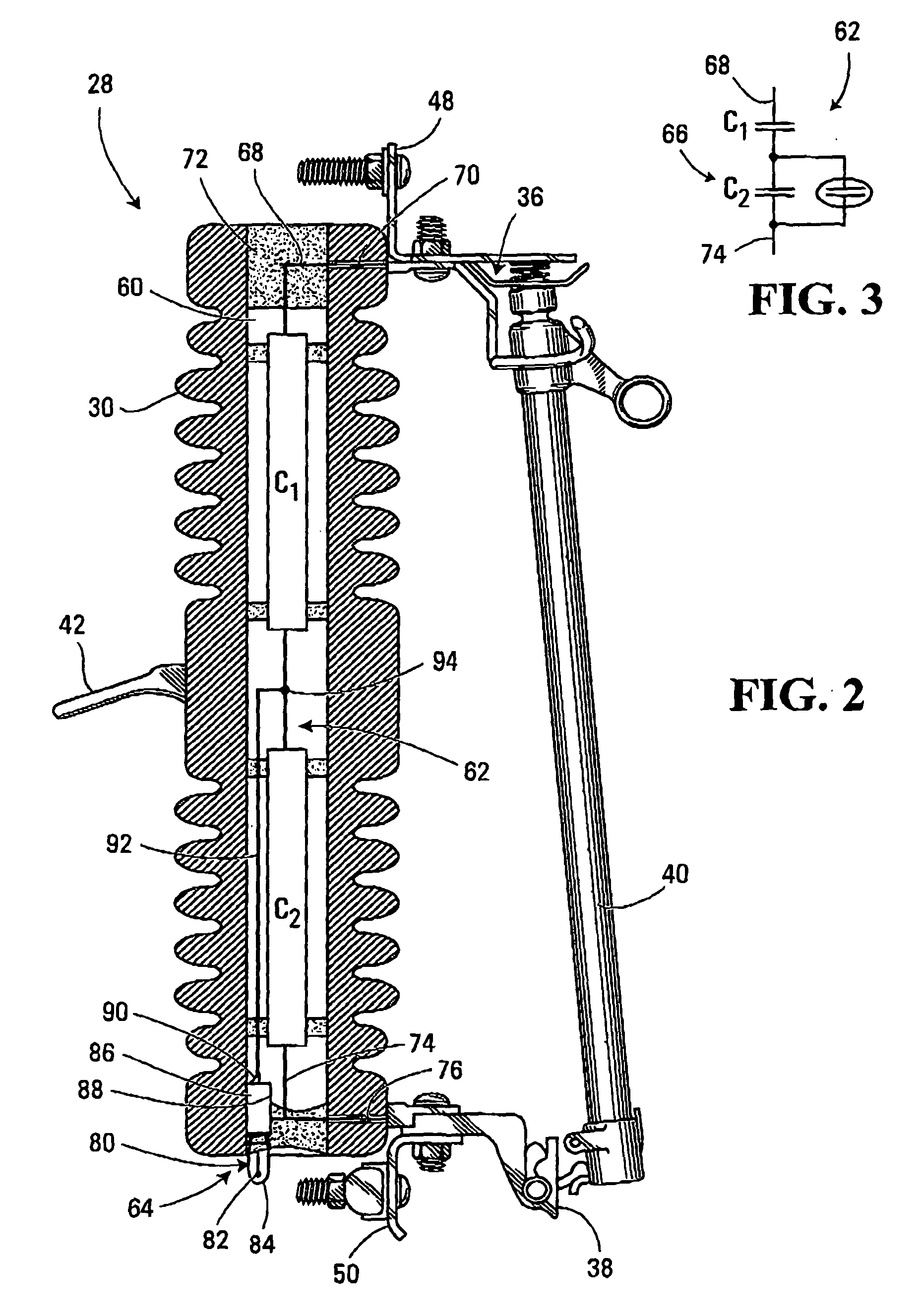
[0040] To the power pole 16 is connected the apparatus according to the first embodiment of the invention, as shown at 28. In this embodiment, the apparatus 28 includes a porcelain insulator 30 having...

second embodiment

[0052] Referring to FIG. 10, an apparatus according to the invention is shown generally at 140. In this embodiment, the apparatus 140 includes a conventional fuse cutout shown generally at 142 and a fault condition monitoring apparatus 144 in the shape of a conventional fuse. The fault condition monitoring apparatus 144 includes a cylindrical housing 146 having a profile of a fuse operable to be held by the fuse cutout 142. The housing 146 has first and second contacts 148 and 150, respectively, operable to make electrical contact with fuse contacts 152 and 154 on the fuse cutout 142 when the housing 146 is supported by the fuse cutout 142. The contacts 148 and 150 are operable to electrically and mechanically mate with the fuse contacts on a fuse cutout. In the embodiment shown, at least one of the contacts, in this case the first contact 148, includes a pull ring for convenient installation into a fuse cutout using a conventional lineman tool known as “hot stick” (not shown).

[0053...

third embodiment

[0056] Referring to FIG. 12, an apparatus according to the invention is shown generally at 170 and includes a tubular housing 172 in which is installed the current sensor shown schematically in broken outline at 156 and a signaling device also shown in broken outline at 158. In this embodiment, however, the contacts 148 and 150 of the apparatus shown in FIG. 11 are eliminated and instead, the apparatus 170 includes first and second connectors 174 and 176 at opposite ends of the housing 172 operable to mate with the first and second line connectors 48 and 50 of a conventional fuse cutout shown generally at 176. The first and second line connectors 48 and 50 include spaced apart studs 178 and 180 and the first and second connectors 174 and 176 on th apparatus 170 include slotted tabs 182 and 184, respectively, having slots 186 and 188, respectively, spaced apart by the same distance as the spacing of the studs 178 and 180 such that the studs 178 and 180 may be received in respective s...


PUM

PropertyMeasurementUnit
voltageaaaaaaaaaa
voltage ratingaaaaaaaaaa
currentaaaaaaaaaa

Abstract

A fault condition monitoring apparatus for use with a fuse cutout includes a housing operable to be supported by the fuse cutout. The housing has first and second contacts operable to make electrical contact with fuse contacts on the fuse cutout when the housing is supported by the fuse cutout. A current sensor is mounted inside the housing and is connected to the first and second contacts. A signaling device is coupled to the current sensor and is operable to cause a signal to be produced when current sensed by the current sensor meets a criterion.

Description

BACKGROUND OF THE INVENTION [0001] 1. Field of Invention [0002] This invention relates to high voltage power distribution systems and more particularly to apparatus and methods for monitoring for a fault condition in such systems [0003] 2. Description of Related Art [0004] Power distribution transformers in a high voltage power distribution system are susceptible to internal and external faults. Internal faults may occur due to gradual degradation and / or sudden breakdown of insulating properties of internal structures of the transformer resulting from thermal, electrical and mechanical stresses. The loss of insulating properties of internal structures can lead to a short circuit within the transformer, creating an internal arcing fault. Such fault may occur in a winding of the transformer, for example. A short circuit of this type usually causes burning of the winding, ultimately resulting in an open circuit in the primary winding, whether the fault was initiated in the primary or s...

Claims


Application Information

Patent Timeline
Patent Type & Authority Applications(United States)
IPC IPC(8): H01F27/40H01H85/30H01H85/32H02H3/04H02H7/04
CPCH01F27/402H01H85/30H02H7/04H01H2071/088H02H3/046H01H85/32
Inventor CUK, NIKOLA
Owner CUK NIKOLA
Why Eureka
Try Eureka