

Wobble signal detecting circuit for optical disk device and wobble signal detecting method
- Summary
- Abstract
- Description
- Claims
- Application Information
AI Technical Summary
Benefits of technology
Problems solved by technology
Method used
Image

Examples
first embodiment
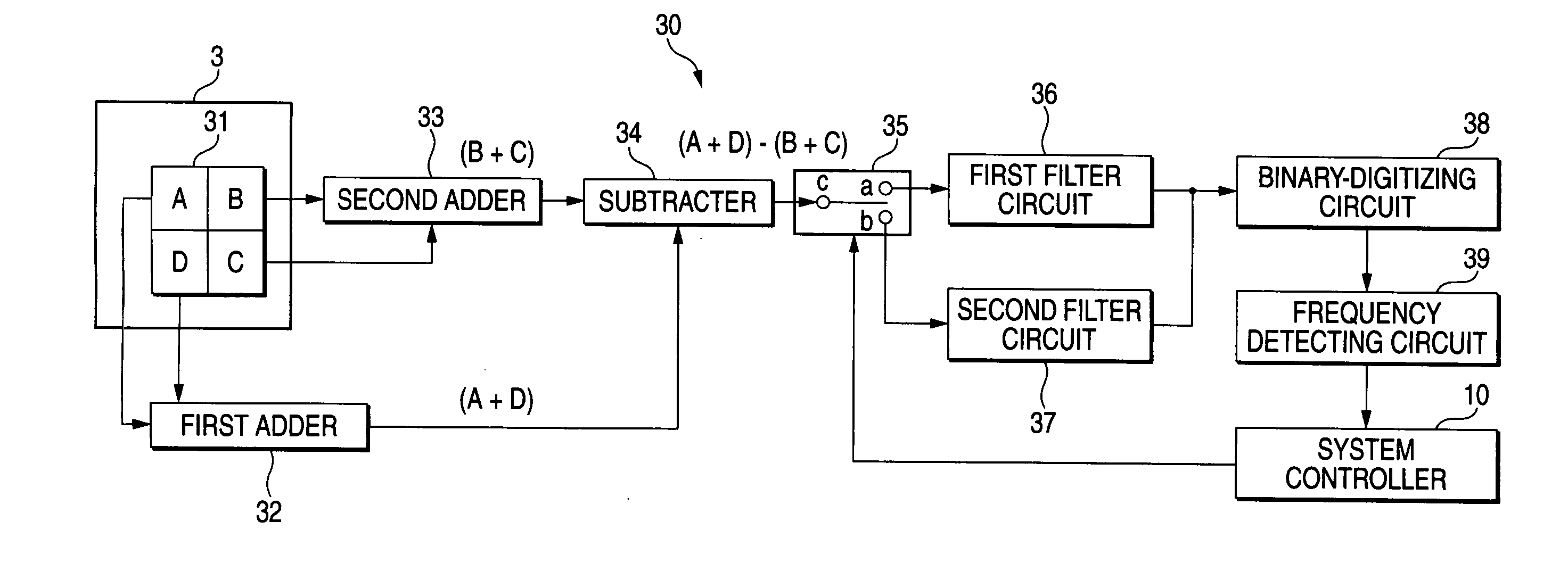
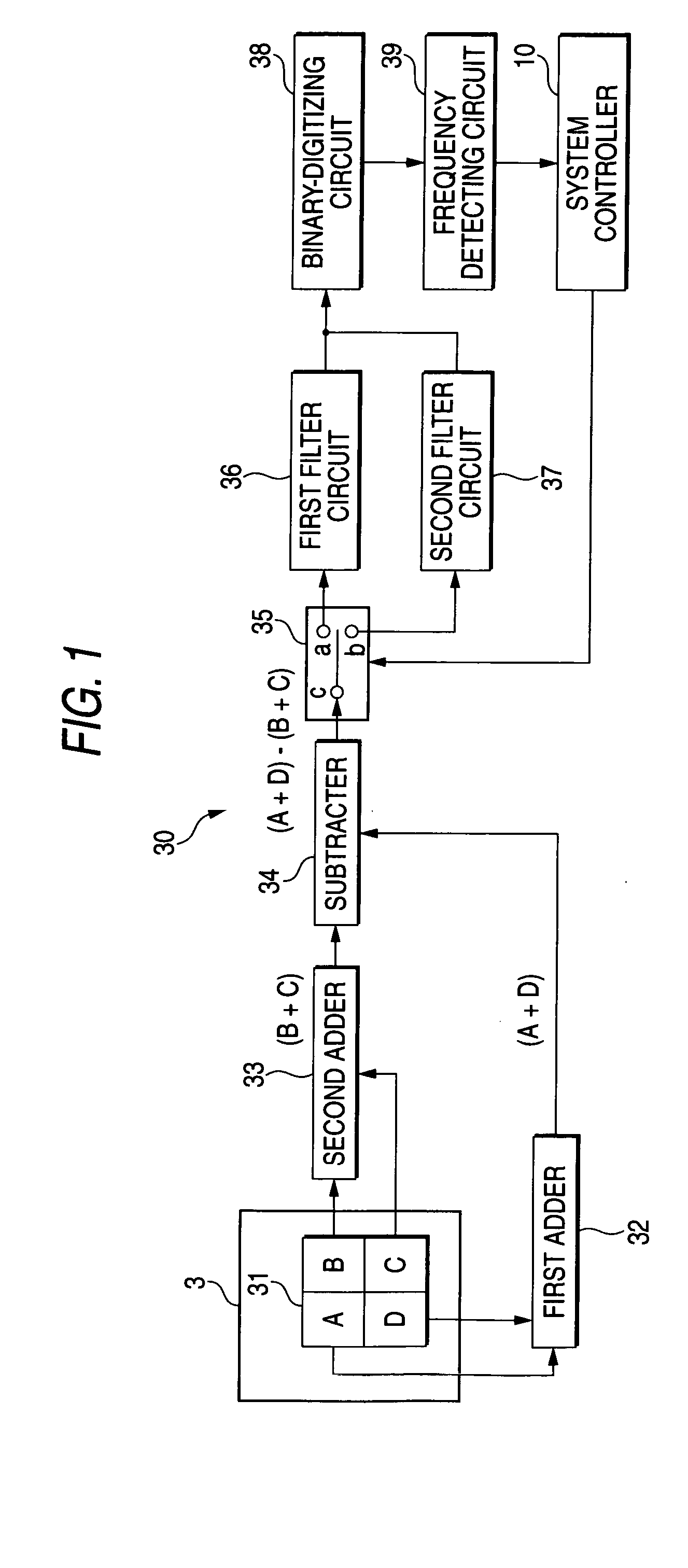
[0048] In the first embodiment, the first filter circuit 36 is constructed of a first band-pass filter 36a, whereas the second filter circuit 37 is constructed of a second band-pass filter 37a.
[0049] In this first embodiment, as shown in FIG. 3B, the first band-pass filter 36a has a bandwidth so that its higher frequency side shoulder (indicated by reference numeral 36a1) is located on the wobble frequency (e.g. 150 kHz). As shown in FIG. 3C, the second band-pass filter 37a has a bandwidth set so that its lower frequency side shoulder (indicated by reference numeral 37a1) is located on the wobble frequency (150 kHz).
[0050] In accordance with the above configuration, with respect to the frequency (150 kHz) of the wobble signal, where the first band-pass filter 36a has the center frequency of 100 kHz and the pass bandwidth of 110 kHz, and the second band-pass filter 37a has the center frequency of 200 kHz and the pass bandwidth of 110 kHz, if the measured signal includes the wobble ...
second embodiment
[0055] In the second embodiment, the first filter circuit 36 is constructed of a band-pass filter 36b, whereas the second filter circuit 37 is constructed of a high-pass filter 37b.
[0056] In this second embodiment, as shown in FIG. 5B, the band-pass filter 36b has a bandwidth set so that its higher frequency side shoulder (indicated by reference numeral 36b1) is located on the wobble frequency (150 kHz). As shown in FIG. 5C, the high-pass filter 37b has a pass band so that its lower frequency side shoulder (indicated by reference numeral 37b1) is located on the wobble frequency (e.g. 150 kHz). In the band-pass filter 36b, the center frequency is set at 100 kHz and the pass bandwidth is set at 110 kHz.
[0057] In accordance with the above configuration, if the measured signal includes the wobble signal S1 as shown in FIG. 5A, through whichever filter of the band-pass filter 36b and high-pass filter 37a, the frequency (frequency of about 150 kHz) in the vicinity of the wobble frequenc...
third embodiment
[0062] In the third embodiment, the first filter circuit 36 is constructed of a low-pass filter 36c, whereas the second filter circuit 37 is constructed of a band-pass filter 37c.
[0063] In this third embodiment, as shown in FIG. 6B, the low-pass filter 36c has a pass band set so that its higher frequency side shoulder (indicated by reference numeral 36c1) is located on the wobble frequency (150 kHz). As shown in FIG. 6C, the band-pass filter 37c has a bandwidth set so that its lower frequency side shoulder (indicated by reference numeral 37c1) is located on the wobble frequency (e.g. 150 kHz). In the band-pass filter 37c, the center frequency is set at 200 kHz and the pass bandwidth is set at 110 kHz.
[0064] In accordance with the above configuration, if the measured signal includes the wobble signal S1 as shown in FIG. 6A, through whichever filter of the low-pass filter 36c and band-pass filter 37c, the frequency (frequency of about 150 kHz) in the vicinity of the wobble frequency...
PUM
 Abstract
Description
Claims
Application Information