Use of wide element spacing to improve the flexibility of a circular base station antenna array in a space division/multiple access synchronous CDMA communication system

Active Publication Date: 2005-10-18
L3 TECH INC
View PDF5 Cites 21 Cited by
  • Summary
  • Abstract
  • Description
  • Claims
  • Application Information

AI Technical Summary

Benefits of technology

[0011]In accordance with an aspect of these teachings, the inventors have found that the use of a wide antenna element spacing improves the flexibility of installation and code assignment in a synchronous code division multiple access (S-CDMA) system utilizing space division multiple access (SDMA). The wide element spacing (i.e., greater than one half w

Problems solved by technology

Sectorization also suffers from decreased Erlang efficiency due to the limited capacity per sector.
As such, since sectorization places restrictions on the locations of users, it is not the most efficient approach to supporting communications within a given area.
This patent also does not consider the S-CDMA case, nor the possibility of reusing the orthogonal spreading codes within the same coverage area.
It is

Method used


Image

  • Use of wide element spacing to improve the flexibility of a circular base station antenna array in a space division/multiple access synchronous CDMA communication system
  • Use of wide element spacing to improve the flexibility of a circular base station antenna array in a space division/multiple access synchronous CDMA communication system
  • Use of wide element spacing to improve the flexibility of a circular base station antenna array in a space division/multiple access synchronous CDMA communication system

Examples


Embodiment Construction

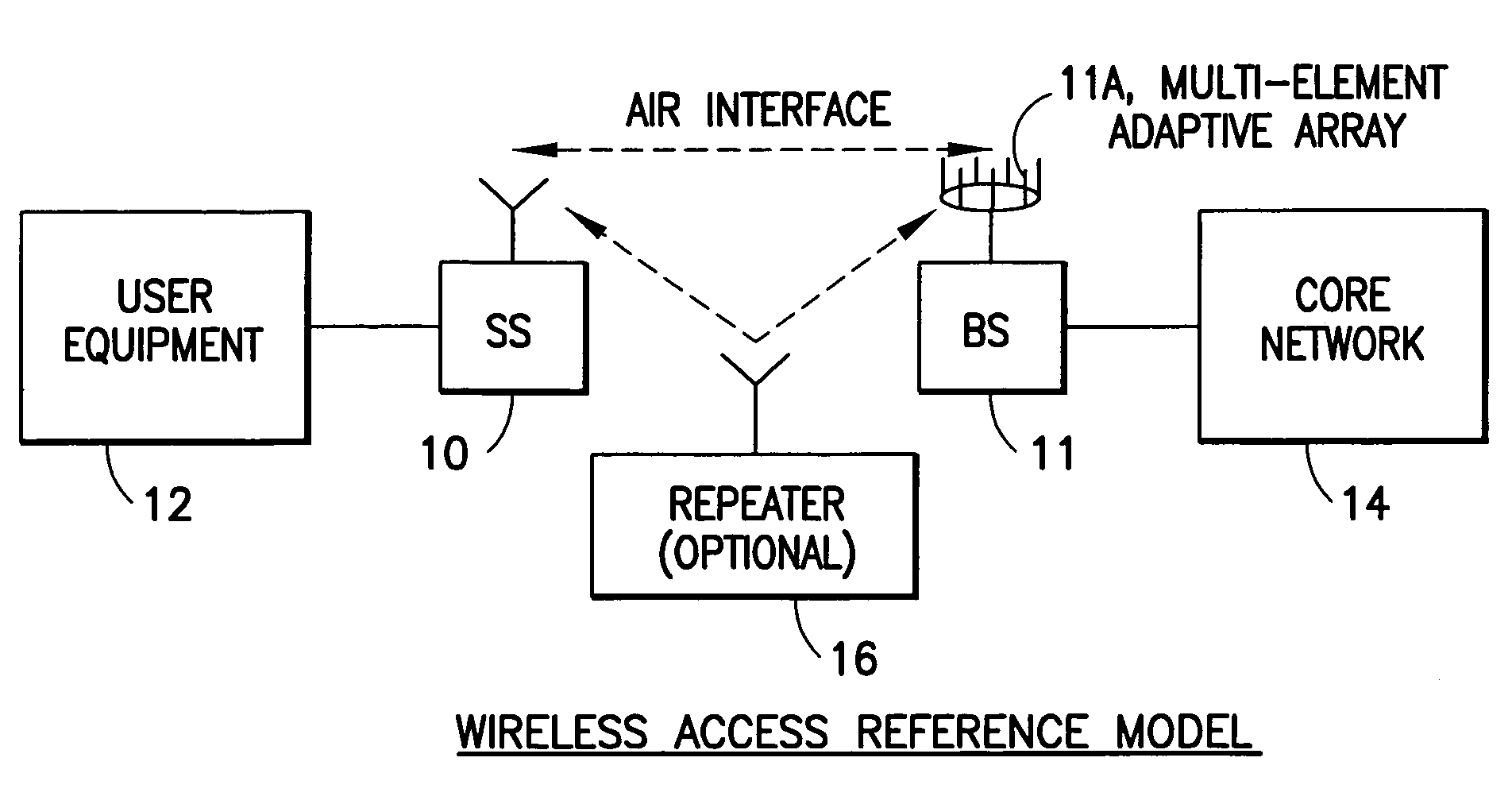
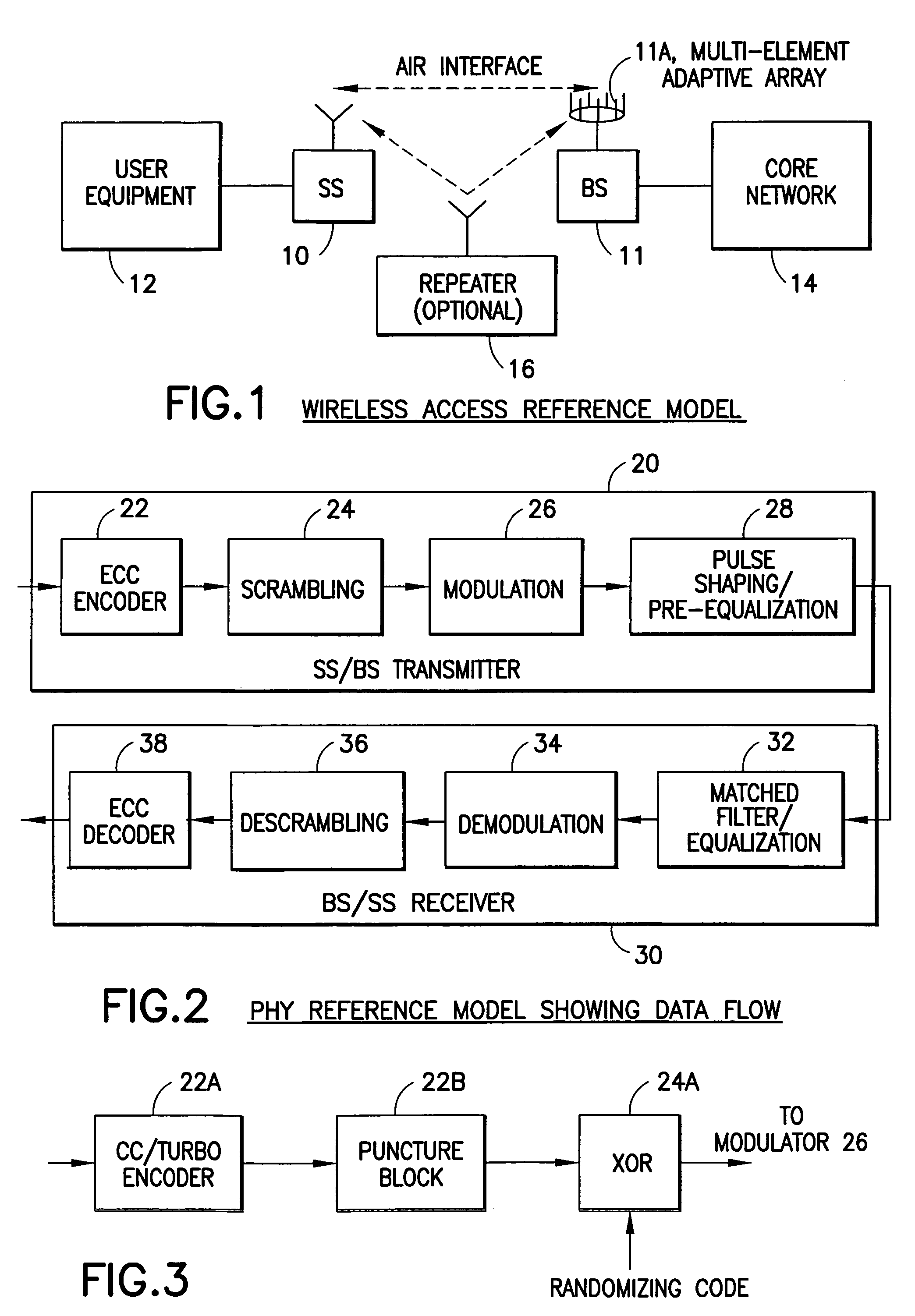
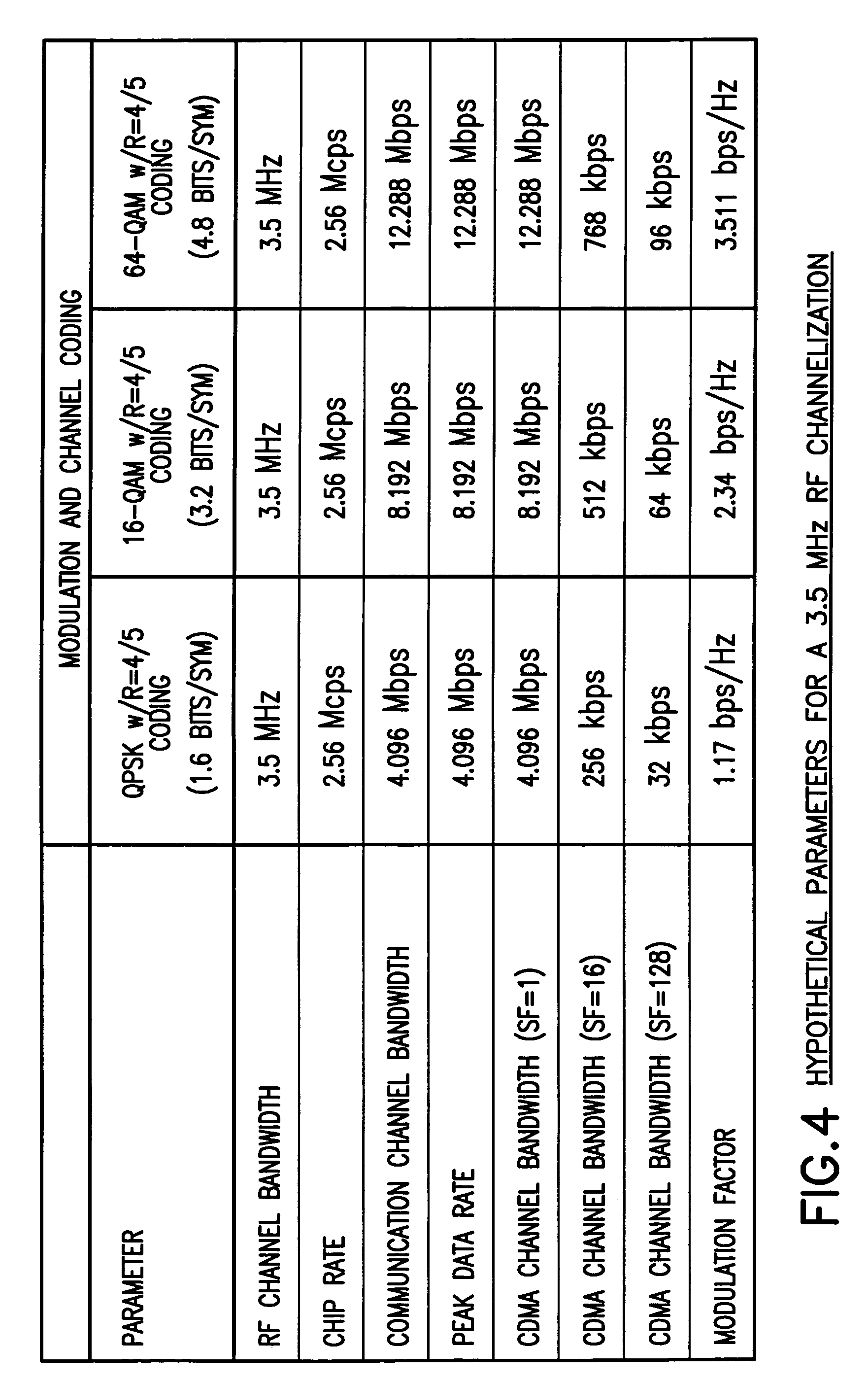
[0027]Disclosed herein is a PHY system intended for IEEE 802.16.3 and related standards, although those having skill in the art should realize that various aspects of these teachings have wider applicability.

[0028]The technique is based on a hybrid synchronous DS-CDMA (S-CDMA) and FDMA scheme using quadrature amplitude modulation (QAM) and trellis coding. For a general background and benefits of S-CDMA with trellis-coded QAM one may refer to R. De Gaudenzi, C. Elia and R. Viola, “Bandlimited Quasi-Synchronous CDMA: A Novel Satellite Access Technique for Mobile and Personal Communication Systems,” IEEE Journal on Selected Areas in Communications, Vol. 10, No. 2, February 1992, pp. 328–343, and to R. De Gaudenzi and F. Gianneti, “Analysis and Performance Evaluation of Synchronous Trellis-Coded CDMA for Satellite Applications,” IEEE Transactions on Communications, Vol. 43, No. 2 / 3 / 4, February / March / April 1995, pp. 1400–1409.

[0029]The ensuing description focuses on a frequency division ...


PUM


Abstract

A method is disclosed for operating a synchronous space division multiple access, code division multiple access communications system, as is a system that operates in accordance with the method. The method operates, within a coverage area of a base station (BS), to assign the same spreading code to a plurality of subscriber stations (SSs) and to transmitting signals to, and receive signals from, the SSs using an antenna array having M elements, where M>1 and where the M elements are spaced apart by more than one-half wavelength from one another. The spacing is a function of a size of an aperture of the antenna array which is a function of a signal bandwidth to carrier frequency ratio. The antenna array aperture is preferably less than k=p/360*fc/B wavelengths, where p is a maximum acceptable phase variation over the signal bandwidth, where fc is the carrier frequency and where B is the signal bandwidth. The step of conducting communications includes steps of despreading a plurality of received signals; and beamforming the plurality of despread received signals. In a preferred embodiment individual ones of P orthogonal spreading codes are reused αM times within the coverage area, where 1/M<α≦1.

Description

CLAIM OF PRIORITY FROM COPENDING PROVISIONAL PATENT APPLICATION[0001]This patent application claims priority from U.S. Provisional Patent Application No. 60 / 243,808, filed on Oct. 27, 2000, the disclosure of which is incorporated by reference herein in its entirety.FIELD OF THE INVENTION[0002]These teachings relate generally to wireless communications systems and methods, and relates in particular to Space Division / Multiple Access implementations for Synchronous Code Division Multiple Access (S-CDMA) systems.BACKGROUND OF THE INVENTION[0003]In a synchronous direct-sequence code division multiple access (S-CDMA) system, users communicate simultaneously using the same frequency band via orthogonal modulation or spread spectrum. The number of orthogonal spreading codes (>1) limits the total capacity of the system. To increase the capacity of a CDMA system in a given service area, without requiring additional frequency bandwidth, space division multiple access (SDMA) can be employed....

Claims


Application Information

Patent Timeline
IPC IPC(8): H01Q1/24H01Q21/20H04B1/707H04L1/00H04Q7/36H04B7/155H04J13/00H04B1/69H04J13/16H04W16/02H04W16/12
CPCH01Q1/246H01Q21/205H04B1/707H04W16/02H04W16/12H04B2201/70703H04B2201/709709H04J13/0074H04J13/16H04L1/0003H04L1/0013
Inventor ERTEL, RICHARD B.GIALLORENZI, THOMAS R.HALL, ERIC K.
Owner L3 TECH INC
Why Eureka
Try Eureka