Techniques for dynamically adjusting the frequency range of phase-locked loops

a phase-locked loop and frequency range technology, applied in the field of electronic circuits, can solve the problems of significant deformation of the performance of the vco and functional failure of the pll

Active Publication Date: 2009-02-24
ALTERA CORP
View PDF12 Cites 23 Cited by
  • Summary
  • Abstract
  • Description
  • Claims
  • Application Information

AI Technical Summary

Benefits of technology

[0006]The present invention provides techniques for dynamically adjusting the frequency range of phase-locked loops (PLLs). Phase detection circuitry in a PLL generates a control signal in response to a periodic input signal and a feedback signal. When the control signal deviates outside a valid range, the input frequency range of the PLL is dy...

Problems solved by technology

If the frequency of the VCO output signal moves outside the valid operating range, the performance of the VCO can degrade substantially.
Depending on the design marg...

Method used


Image

  • Techniques for dynamically adjusting the frequency range of phase-locked loops
  • Techniques for dynamically adjusting the frequency range of phase-locked loops
  • Techniques for dynamically adjusting the frequency range of phase-locked loops

Examples


Embodiment Construction

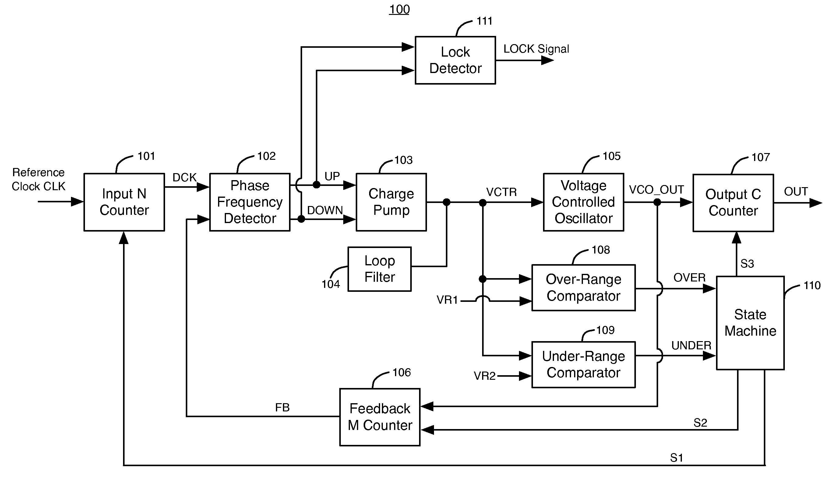
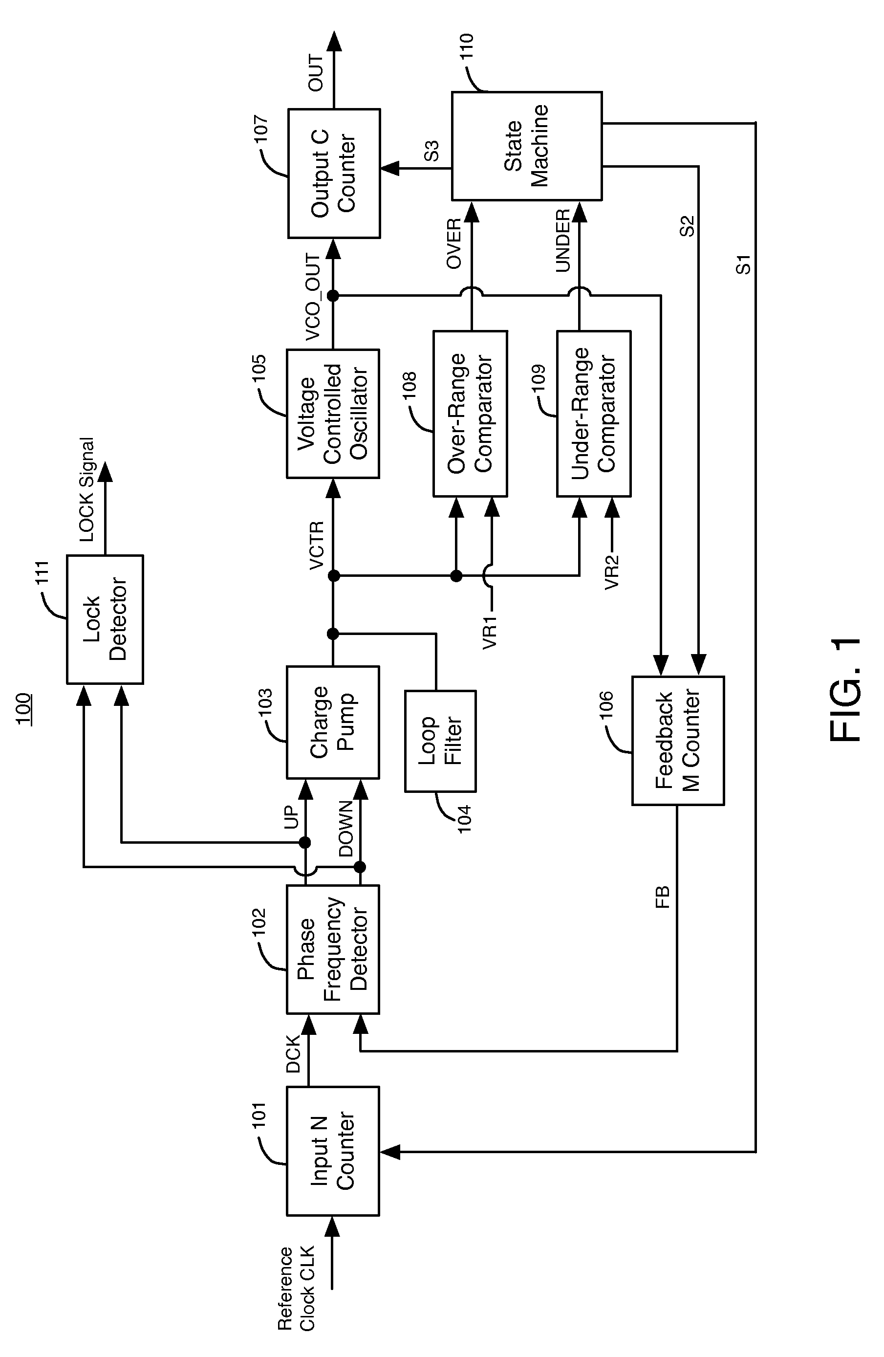
[0014]FIG. 1 illustrates a phase-locked loop (PLL) 100, according to a first embodiment of the present invention. PLL 100 includes input N counter 101, phase and frequency detector (PFD) 102, charge pump 103, loop filter 104, voltage controlled oscillator (VCO) 105, feedback M counter 106, output C counter 107, over-range comparator 108, under-range comparator 109, state machine 110, and lock detector 111.

[0015]Input N counter circuit 101 receives an input reference clock signal CLK at its input terminal. Counter 101 adjusts the frequency of clock signal CLK by a frequency ratio N to generate a periodic input signal DCK. For example, counter 101 can multiply or divide the frequency of the clock signal to generate DCK. The periodic input signal DCK is transmitted to a first input of phase and frequency detector (PFD) 102. A feedback signal FB is transmitted from the output of feedback counter 106 to a second input of PFD 102.

[0016]Phase and frequency detector 102 and charge pump 103 ...


PUM


Abstract

Techniques are provided for dynamically adjusting the frequency range of phase-locked loops (PLLs). Phase detection circuitry in a PLL generates a control signal in response to a periodic input signal and a feedback signal. When the control signal deviates outside a valid range, the input frequency range of the PLL is dynamically adjusted to include the periodic input signal frequency. The input frequency range of the PLL is adjusted by changing one or more frequency ratios in the PLL. The resistance and/or capacitance of a loop filter in the PLL can be dynamically adjusted to control the bandwidth of the PLL.

Description

BACKGROUND OF THE INVENTION[0001]The present invention relates to electronic circuits, and more particularly, to phase-locked loop circuits.[0002]A phase-locked loop (PLL) is an electronic circuit with an oscillator. A PLL adjusts the frequency of a feedback signal from the output of the oscillator to match in phase the frequency of an input reference clock signal. Phase-locked loops (PLLs) are an essential building block of many integrated circuits, providing periodic signals for data recovery, data transfer, and other clocking functions. PLLs often supply a clock signal to one or more counters or dividers that divide a signal from the oscillator to a lower frequency clock signal for distribution around an integrated circuit or system.[0003]A PLL can be used to stabilize a particular communications channel (i.e., keeping it set to a particular frequency). A PLL can also be used to generate a signal, modulate or demodulate a signal, reconstitute a signal with less noise, or multiply...

Claims


Application Information

Patent Timeline
IPC IPC(8): H03L7/06H03L7/093H03L7/095H03L7/099H03L7/18
CPCH03L7/093H03L7/099H03L7/18H03L7/0891H03L7/095Y10S331/02
Inventor HOANG, TIM TRISHUMARAYEV, SERGEY
Owner ALTERA CORP
Why Eureka
Try Eureka