Push-type rivetless nut plate and method and apparatus for installing same

a technology push-type rivet, which is applied in the direction of threaded fasteners, screwdrivers, manufacturing tools, etc., can solve the problems of rivetless nut plate flaring, screwless nut plate, cumbersome, slow, etc., and achieve the effect of simplifying the installation of rivetless nut plates

Inactive Publication Date: 2005-02-03
SPS TECH LLC
View PDF84 Cites 36 Cited by
  • Summary
  • Abstract
  • Description
  • Claims
  • Application Information

AI Technical Summary

Benefits of technology

[0015] A primary object of the invention is to provide a push-type rivetless nut

Problems solved by technology

The installation of rivetless nut plates with tooling of present designs, however, such as those discussed in U.S. Pat. No. 4,732,518, is cumbersome, slow, complicated, costly and often non-functional.
The flaring of rivetless nut plates is also disadvantageous for many reasons, such as complicated tooling, special aperture preparation (such as counter-bore and counter-sink) to achieve flush installation, grip length limitations, the creation of gaps between the sleeve and the walls of the workpiece, and longer length, thus making the rivetless nut plate a relatively heavy component.
The parts for this design are very expensive, installation is costly and cumbersome, and hole preparation needs to be very precise.
Thus, the overall co

Method used


Image

  • Push-type rivetless nut plate and method and apparatus for installing same
  • Push-type rivetless nut plate and method and apparatus for installing same
  • Push-type rivetless nut plate and method and apparatus for installing same

Examples


first embodiment

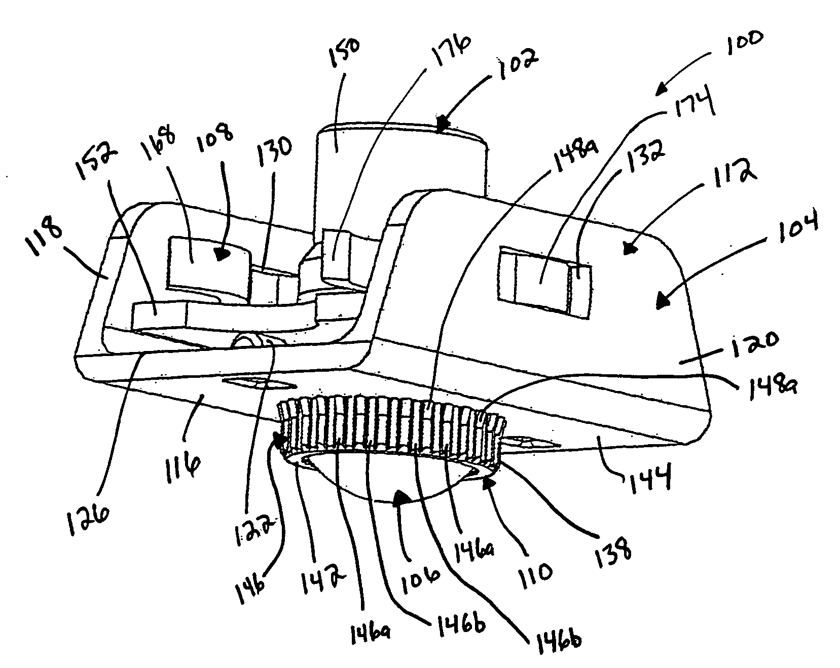
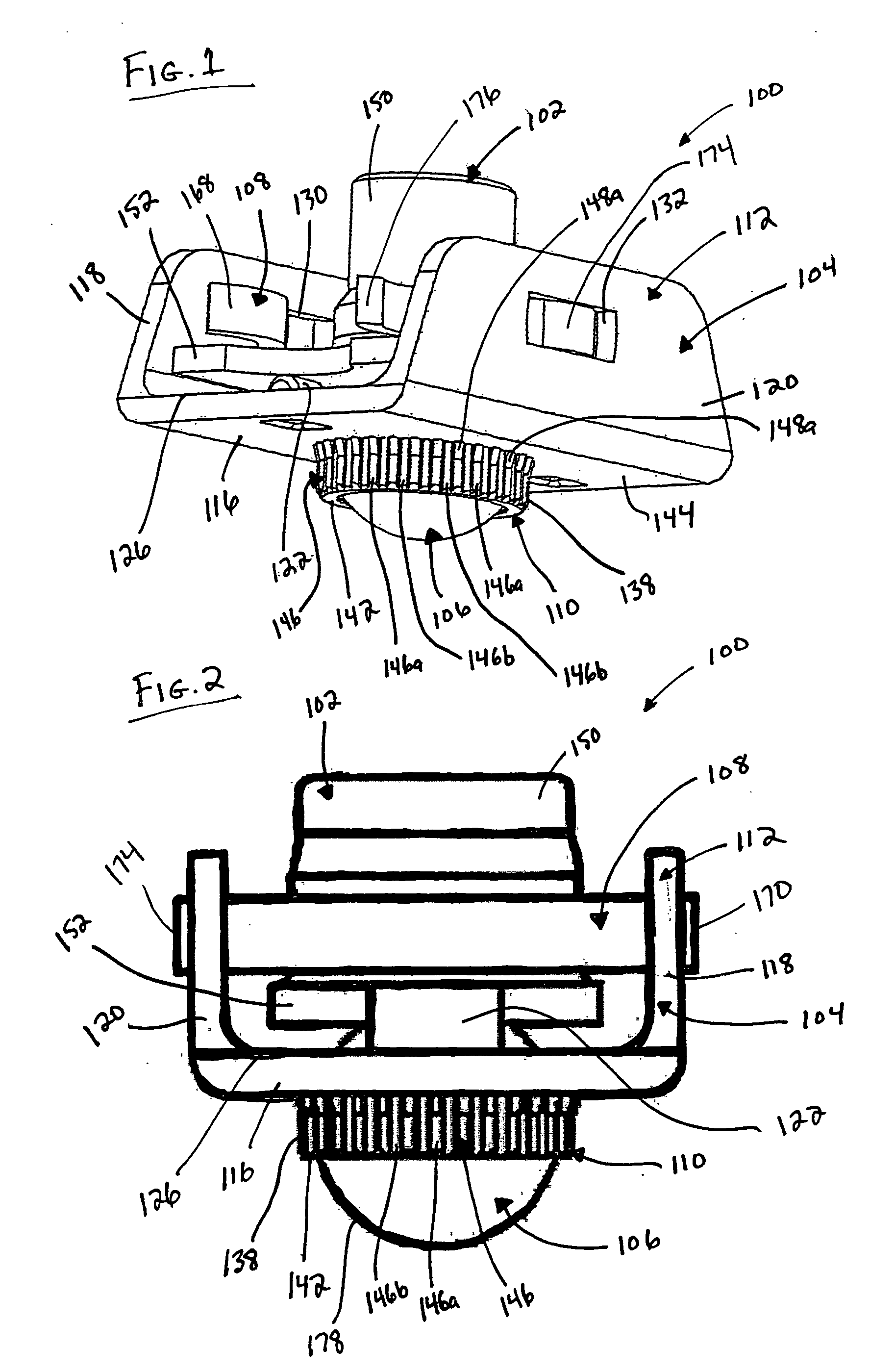
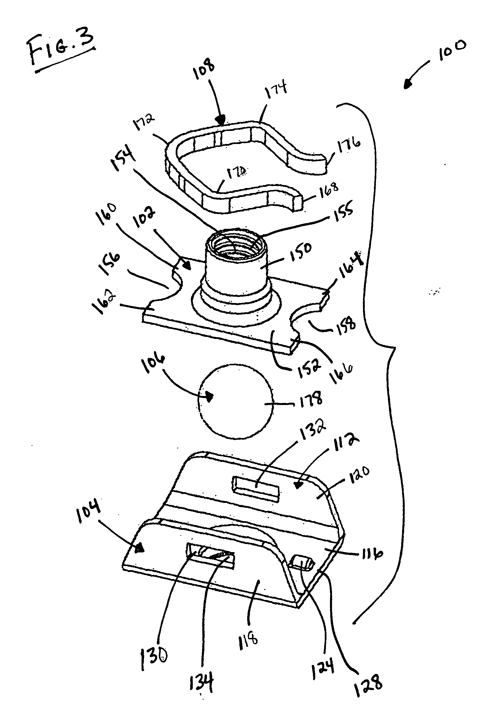
[0063] Thus, the nut 102, the holding bracket 104, the ball 106 and the retainer 108 are preferably preassembled together to form the nut plate 100 of the invention prior to the nut plate 100 being used in operation.

[0064] In operation, the nut plate 100 is secured to a workpiece 180 by inserting the tubular portion 110 of the holding bracket 104 into an aperture 182 of the workpiece 180, such that the undersurface 144 of the bracket portion 112 of the holding bracket 104 sits on a top surface 184 of the workpiece 180, as illustrated in FIGS. 5-7. The aperture 182 has a diameter which is slightly larger than a diameter of the tubular portion 110 of the holding bracket 104, which includes the lobes 146. The aperture 182 has a length which is preferably larger than or equal to a length of the tubular portion 110 of the holding bracket 104 such that the tubular portion 110 does not extend beyond a bottom surface 186 of the workpiece 180.

[0065] Once the nut plate 100 is properly positi...

second embodiment

[0081] Thus, the nut 302, the holding bracket 304, the mandrel 306 and the retainer 308 are preferably preassembled together to form the nut plate 300 of the invention prior to the nut plate 300 being used in operation.

[0082] In operation, the nut plate 300 is secured to a workpiece 380 by inserting the tubular portion 310 of the holding bracket 304 into an aperture 382 of the workpiece 380, such that the undersurface 344 of the bracket portion 312 of the holding bracket 304 sits on a top surface 384 of the workpiece 380, as illustrated in FIGS. 12-14. The aperture 382 has a diameter which is slightly larger than a diameter of the tubular portion 310 of the holding bracket 304, which includes the lobes 346. The aperture 382 has a length which is preferably larger than or equal to a length of the tubular portion 310 of the holding bracket 304 such that the tubular portion 310 does not extend beyond a bottom surface 386 of the workpiece 380.

[0083] Once the nut plate 300 is properly p...


PUM

PropertyMeasurementUnit
Forceaaaaaaaaaa
Diameteraaaaaaaaaa
Lengthaaaaaaaaaa

Abstract

A rivetless nut plate has a nut, a holding bracket, a member and a nut retainer. The nut is provided with an aperture therethrough and is secured within a bracket portion of the holding bracket by the retainer but also is permitted limited movement within the bracket portion. The holding bracket further includes a tubular portion having inner and outer walls. The inner wall is tapered such that the member is positioned against the inner wall. Upon an axial force being applied to the member through the aperture of the nut, the member is pushed through the tubular portion from the first end to the second end in order to expand the inner wall and force the outer wall into engagement with the wall of the workpiece. A tool is provided to push the member through the tubular member and can be incorporated into either a manual or automatic process.

Description

CROSS-REFERENCE [0001] This patent application is a Continuation-In-Part of U.S. patent application Ser. No. 10 / 272,721, filed Oct. 17, 2002, and entitled “Nut Plate”, which, in turn, claims the benefit of domestic priority of U.S. Provisional Application Ser. No. 60 / 345,105, filed Nov. 9, 2001, and entitled “Nutplate”. INCORPORATION BY REFERENCE [0002] The entire disclosure of U.S. patent application Ser. No. 10 / 272,721, filed Oct. 17, 2002, and entitled “Nut Plate”, of which the present application is a Continuation-In-Part patent application, is incorporated herein by reference in its entirety. The disclosure of U.S. patent application Ser. No. 10 / 272,721 is incorporated herein by reference in its entirety solely for brevity purposes. U.S. patent application Ser. No. 10 / 272,721 was published by the United States Patent and Trademark Office on May 15, 2003 as Publication No. US-2003-0091408-A1. BACKGROUND OF THE INVENTION [0003] The present invention relates to a rivetless nut pla...

Claims


Application Information

Patent Timeline
IPC IPC(8): F16B37/04F16B37/06
CPCB21K25/00Y10T29/53B23P19/062F16B37/044F16B37/062F16B37/065Y10T29/49837Y10T29/49947Y10T29/49835Y10T29/49945Y10T29/4994Y10T29/49948Y10T29/49938Y10T29/49833B23P9/025F16B39/28F16B37/06F16B37/04
Inventor TOOSKY, RAHMATOLLAH F.
Owner SPS TECH LLC
Why Eureka
Try Eureka