
Diagnostic device and method of using same

a diagnostic device and testing method technology, applied in the field of clinical diagnostic testing devices, can solve the problems of waste management problems, limited use of sticks solely for ph detection, lack of inexpensive, convenient techniques for supporting the performance of diagnostic steps, etc., to improve safe waste management and convenient use

Inactive Publication Date: 2005-02-03
SINSKY JEROME L +1
View PDF3 Cites 2 Cited by
  • Summary
  • Abstract
  • Description
  • Claims
  • Application Information

AI Technical Summary

Benefits of technology

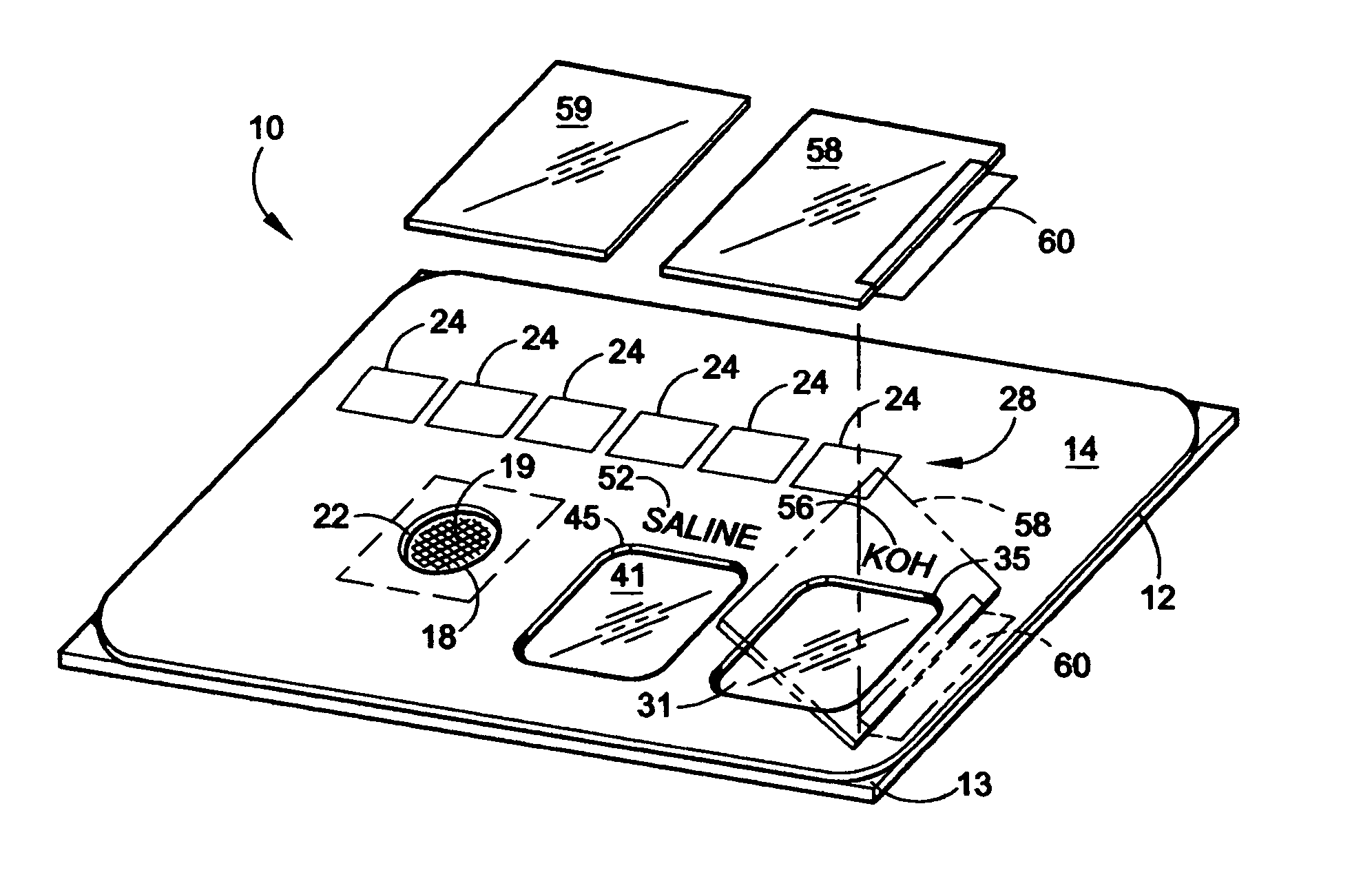
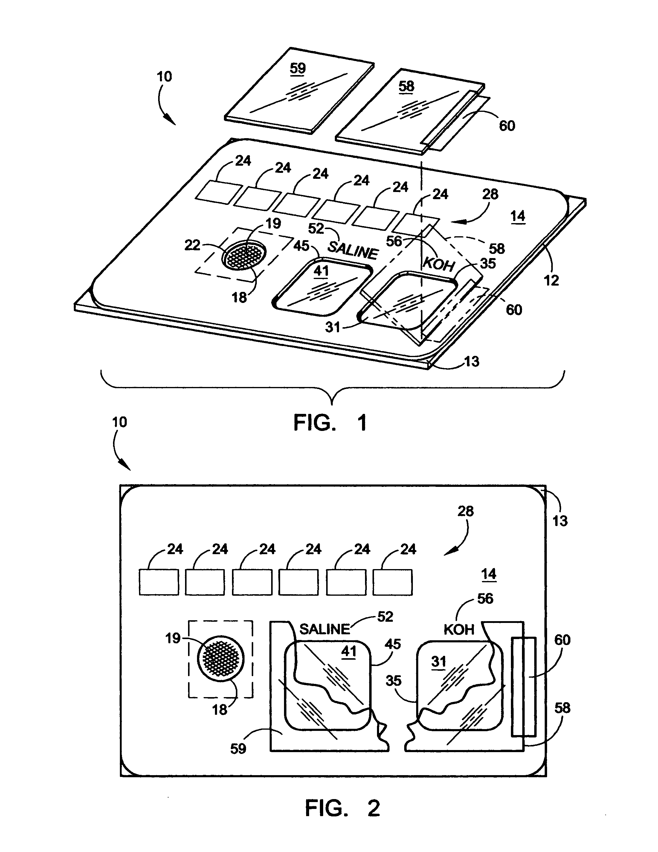
[0011] A diagnostic device embodying the invention is easy and convenient to use and mechanically simple. It enables the grouping of components in a relatively small, easily reached countertop area and helps improve safe waste management by reducing the number of contaminated implements requiring disposal.

Problems solved by technology

While the stick has some utility, it presents a waste management problem after use, as the clinician attempts to dispose of it.
In addition, the stick is limited in use solely for pH detection.
At the present time, there is a lack of inexpensive, convenient techniques for supporting performance of the diagnostic steps.
Performance of the wet mount tests complicates the matter since handling of fluid and reagents of samples for microscopic examination can be cumbersome.
After microscopic examination, of course, the waste management problem is presented once again as disposal of wet slides, pH paper, pH sticks and transport containers or vials becomes necessary.
The above-mentioned conventional techniques are awkward to perform, time consuming and can present a problem in disposal of wet materials, possibly carrying pathogens.
Many clinicians, therefore, skip one or more of these diagnostic steps and try to rely on guesswork to make a diagnosis here and this has been shown in studies to result in diagnostic and treatment errors.

Method used


Image

  • Diagnostic device and method of using same
  • Diagnostic device and method of using same

Examples


Embodiment Construction

[0015] The present invention may be embodied in other specific forms without departing from its spirit or essential characteristics. The described embodiments are to be considered in all respects only as illustrative and not restrictive. The scope of the invention is, therefore, indicated by the appended claims rather than by the foregoing description. All changes that come within the meaning and range of equivalency of the claims are to be embraced within their scope.

[0016] In the following detailed description and in the several figures of the drawings, like elements are identified with like reference numerals.

[0017] As shown in the drawings for purposes of illustration, the invention is embodied in a novel diagnostic device for enabling effective and efficient real time diagnosis of a medical condition. The diagnosis comprises both gross examination and microscopic examination of a bodily fluid by means of a device that is simple and convenient to use and, as one piece, is rela...


PUM

PropertyMeasurementUnit
heightaaaaaaaaaa
heightaaaaaaaaaa
pHaaaaaaaaaa

Abstract

A diagnostic device for use in performing clinical tests on a fluid, including a light transmitting plate and a panel adhered to and substantially covering the plate. The panel has an opening therein formed and a strip of pH testing material, substantially smaller than the panel, is fixed between the plate and the panel to fill substantially the opening, wherein the pH testing material produces a color indicative of fluid pH upon contact with the fluid. A window formed in the panel exposes a portion of the plate wherein the panel forms a wall on the perimeter of the window to confine fluid applied to the plate, within an area defined by the window.

Description

BACKGROUND OF THE INVENTION [0001] The present invention relates generally to clinical diagnostic testing devices and, more particularly, to such devices as utilized by physicians in their offices. [0002] It is recognized that in the case of many pathological conditions, early identification and treatment can substantially reduce subsequent patient suffering. In this regard, testing of female vaginal samples has become recognized as important to the health of a patient. [0003] The problem of vaginitis is one of the most common complaints bringing patients to physician's offices or clinics. The diagnosis is made after examination of vaginal fluid and testing of fluid pH, and a microscopic examination of the fluid. [0004] In order for the test be competently performed, the pH of the fluid should be measured. Changes in pH can be, visually observed. For example, a vaginal pH sampler, having pH paper mounted at the end of a plastic stick can be used to sample the vagina directly. While ...

Claims


Application Information

Patent Timeline
Patent Type & Authority Applications(United States)
IPC IPC(8): B01L3/00B01L99/00
CPCB01L3/5085B01L2300/0822B01L9/54B01L1/52
Inventor SINSKY, JEROME L.GYBEN, CHRISTOPHER J.
Owner SINSKY JEROME L
Learn More