
Mobile communicatiion system, mobile communication terminal, power control method used therefor, and program therefor

Inactive Publication Date: 2005-02-03
LENOVO INNOVATIONS LTD HONG KONG
View PDF6 Cites 109 Cited by
  • Summary
  • Abstract
  • Description
  • Claims
  • Application Information

AI Technical Summary

Benefits of technology

[0022] As is obvious from the above aspects, the mobile communication system of the present invention proposes a method of controlling the downlink transmission power of a CDMA (Code Division Multiple Access) mobile communication terminal (UE: User Equipment) in order to improve the above problem.

Problems solved by technology

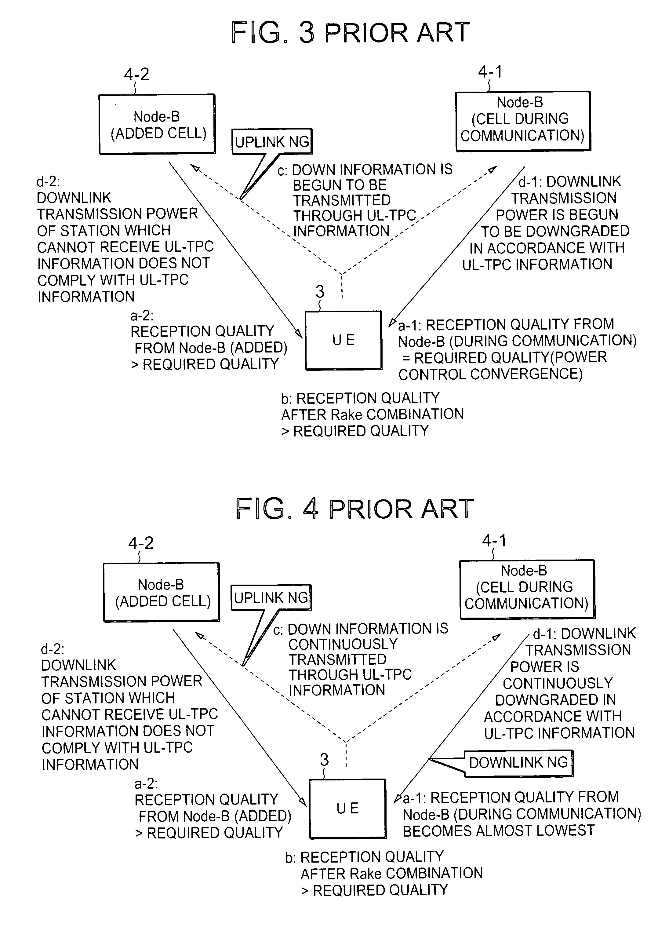
When, however, a mobile communication terminal is performing soft handover communication with a plurality of base stations, i.e., a plurality of downlink wireless links are present, the following problems arise.
In this case, since no power control for downlink transmission power is performed between the base station 4-2 and the mobile communication terminal 3, the power of the mobile communication terminal 3 may be inappropriate for satisfying the required quality.
In such a phenomenon, any Rake combination gain based on handover cannot be obtained.

Method used


Image

  • Mobile communicatiion system, mobile communication terminal, power control method used therefor, and program therefor
  • Mobile communicatiion system, mobile communication terminal, power control method used therefor, and program therefor
  • Mobile communicatiion system, mobile communication terminal, power control method used therefor, and program therefor

Examples


first embodiment

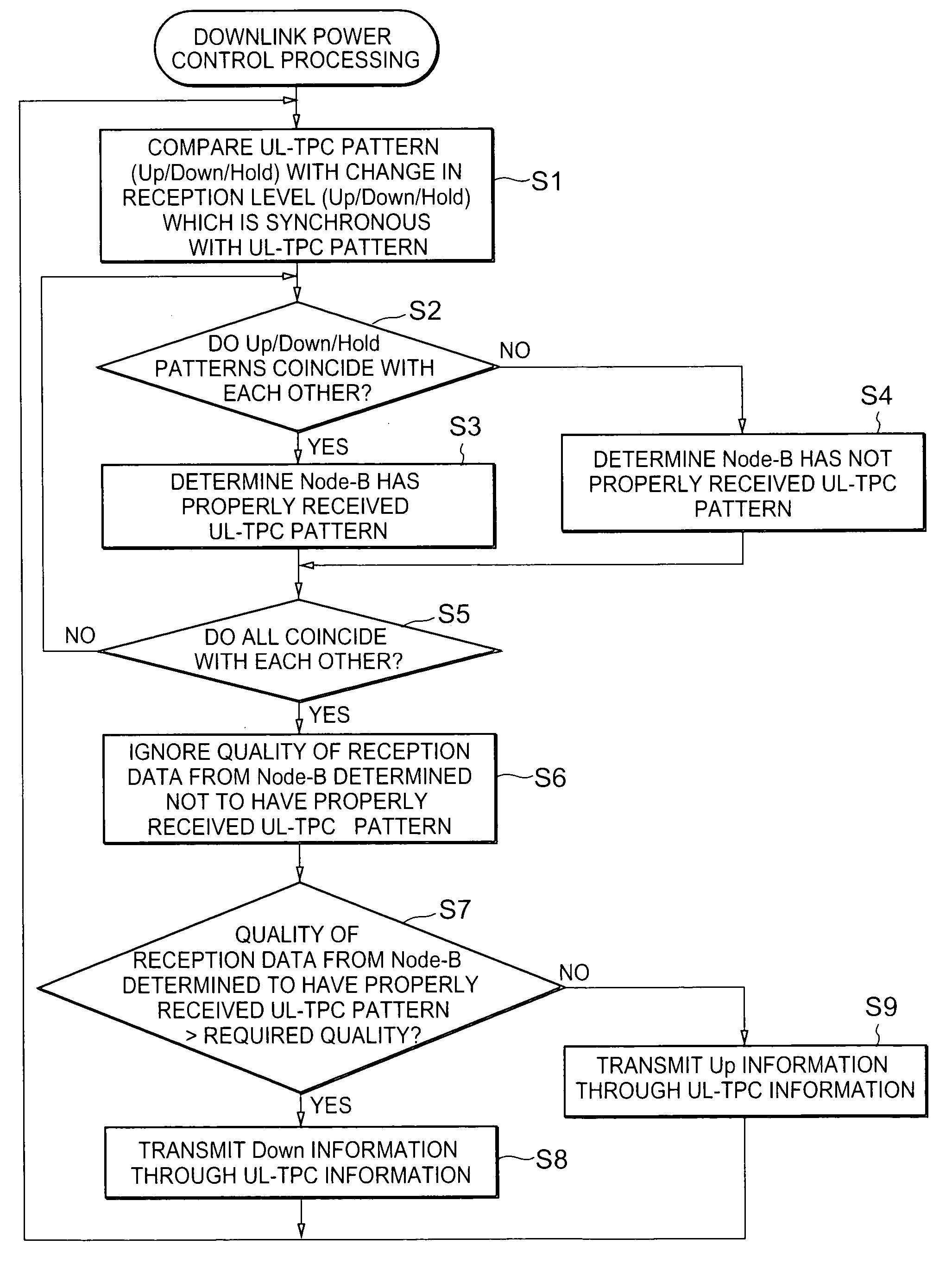
[0045]FIG. 6 is a block diagram showing the arrangement of a mobile communication terminal according to an embodiment of the present invention. Referring to FIG. 6, a mobile communication terminal 1 is comprised of a wireless transmission / reception unit 11, downlink power control unit 12, UL-TPC pattern storage unit 13, reception level change storage unit 14, comparator 15, reception data quality detection unit 16, and recording medium 17. Note that the mobile communication terminal 1 indicates the mobile communication terminal 1 of the mobile communication system according to the embodiment of the present invention shown in FIG. 5. A program (computer-executable program) for implementing each unit of the mobile communication terminal 1 is stored in the recording medium 17.

[0046] The wireless transmission / reception unit 11 transmits / receives data, control signals, and the like to / from base stations (not shown) by radio. The downlink power control unit 12 controls the downlink trans...

second embodiment

[0058]FIG. 8 is a flowchart showing the operation of a mobile communication terminal according to another embodiment of the present invention. Another embodiment of the present invention has the system arrangement shown in FIG. 5, and a mobile communication terminal used in this arrangement has the arrangement shown in FIG. 6. The operation of the mobile transmission terminal of this embodiment will be described with reference to FIGS. 5, 6 and 8. Note that the processing shown in FIG. 8 can be implemented by causing a computer forming a mobile communication terminal 1 execute a program in a recording medium 17.

[0059] During handover communication with a plurality of base stations 2-1 and 2-2, the mobile communication terminal 1 checks whether the downlink transmission power of each of the base stations 2-1 and 2-2 complies with the downlink transmission power control bit (UL-TPC information) transmitted from the self-terminal.

[0060] More specifically, the mobile communication ter...


PUM


Abstract

This invention is directed to a mobile communication system in which the downlink transmission power of a base station is controlled in accordance with a power control bit from a mobile communication terminal, a mobile communication terminal, a power control method, and a program. According to the invention, in order to reliably perform power control even during soft handover communication with a plurality of cells, a determination unit is provided which determines whether the downlink transmission power of a base station complies with the power control bit transmitted from the mobile communication terminal.

Description

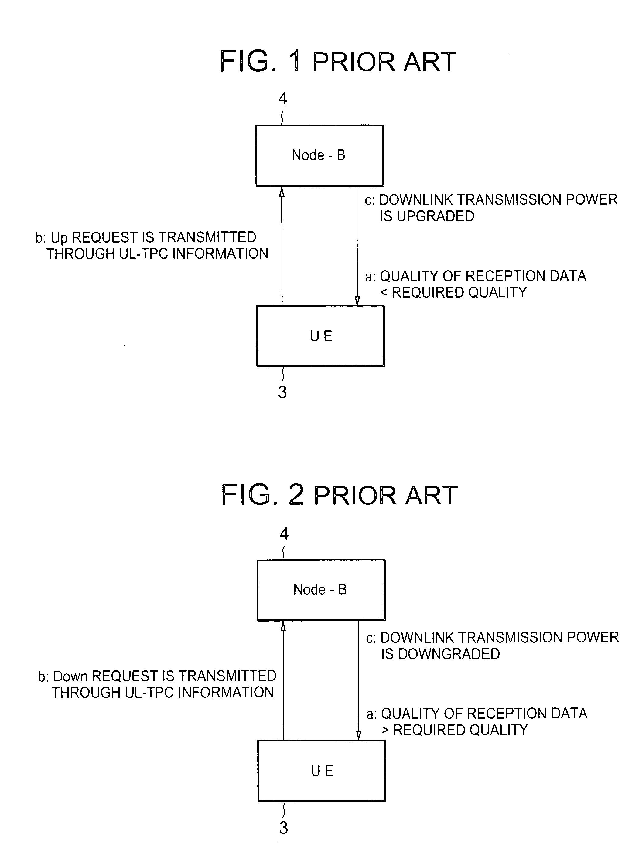
BACKGROUND OF THE INVENTION [0001] 1. Field of the Invention [0002] The present invention relates to a mobile communication system, a mobile communication terminal, and a power control method used therefor, and a program therefor and, more particularly, to a power control method in a CDMA (Code Division Multiple Access) mobile communication terminal. [0003] 2. Description of the Prior Art [0004] In a conventional CDMA mobile communication system, as shown in FIGS. 1 and 2, Up / Down / Hold of downlink transmission power from a base station (Node-B) 4 is controlled by a downlink transmission power control bit (UL-TPC (Up Link-Transmit Power Control) information) from a mobile communication terminal (UE: User Equipment) 3. [0005] The mobile communication terminal 3 always checks whether the quality of downlink reception data satisfies the required quality defined for each service (“a” in FIGS. 1 and 2). If the quality satisfies the required quality, the mobile communication terminal 3 tra...

Claims


Application Information

Patent Timeline
IPC IPC(8): H04B7/005H04B7/26H04J13/00H04W52/04H04W52/08H04W52/40
CPCH04W52/143H04W52/40H04W52/228H04W52/221
Inventor HOKAO, TOMOAKI
Owner LENOVO INNOVATIONS LTD HONG KONG
Learn More