Contact lens cleansing unit

a technology for cleaning units and contact lenses, applied in the direction of disinfection, cleaning processes and apparatuses, and cleaning using liquids, can solve the problems of ineffective liquid current, unstable vibration, and weakening elasticity, and achieve the effect of facilitating maintenance and total cleaning and disinfection

Inactive Publication Date: 2005-02-10
LAI JUNG HUA
View PDF4 Cites 39 Cited by
  • Summary
  • Abstract
  • Description
  • Claims
  • Application Information

AI Technical Summary

Benefits of technology

[0008] The object of the invention is to achieve total cleaning and disinfecting through the combination of

Problems solved by technology

Although the aforesaid contact lens cleaning/disinfecting system can accomplish the job of cleaning and disinfecting, but the vibrations are unstable and easily shifted, plus the liquid current is not effective.
With passing of

Method used


Image

  • Contact lens cleansing unit
  • Contact lens cleansing unit
  • Contact lens cleansing unit

Examples


Embodiment Construction

[0015] To better understand the characteristics and novelties of the invention, descriptions shall be given with the accompanying drawings hereunder.

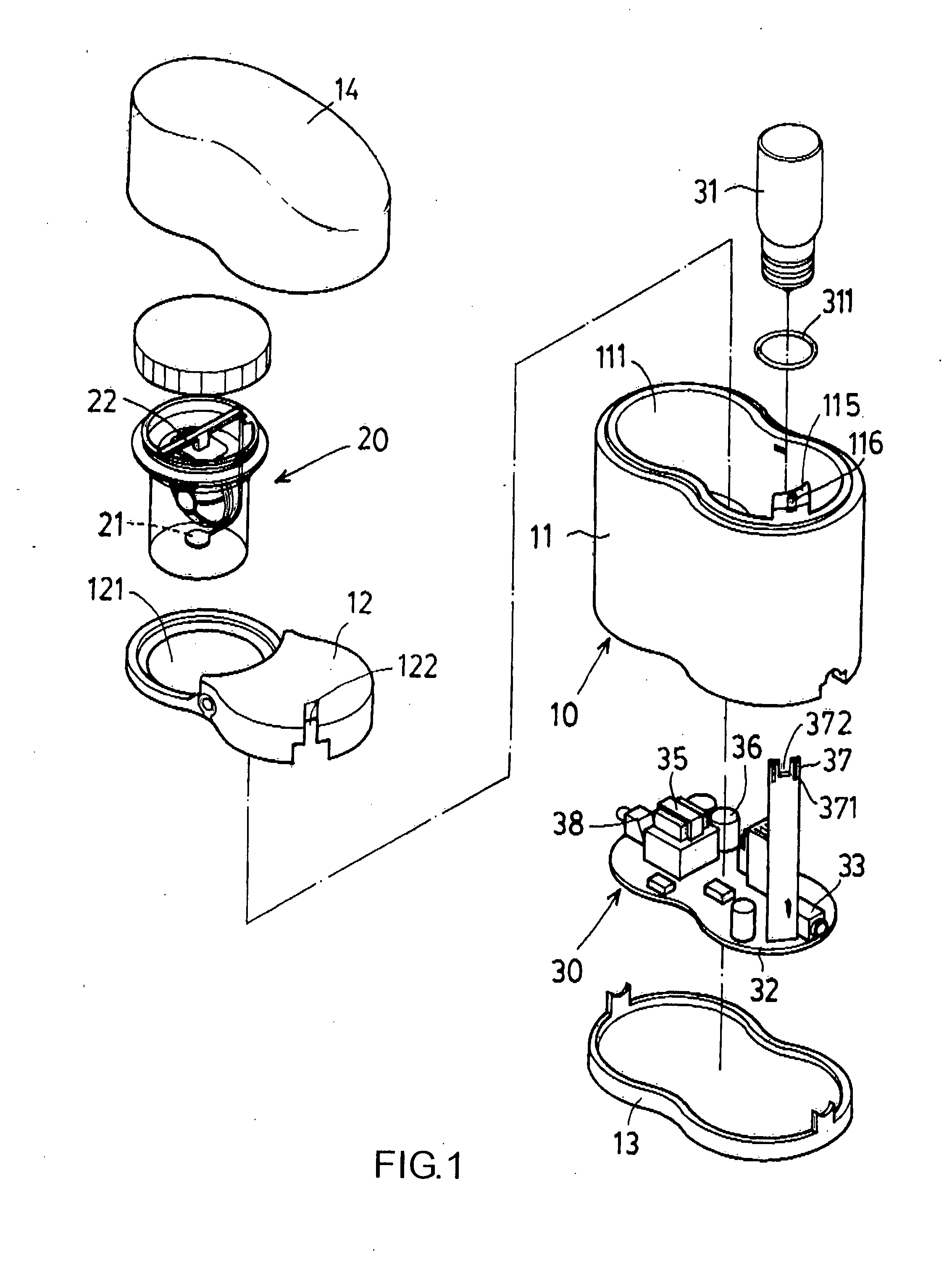
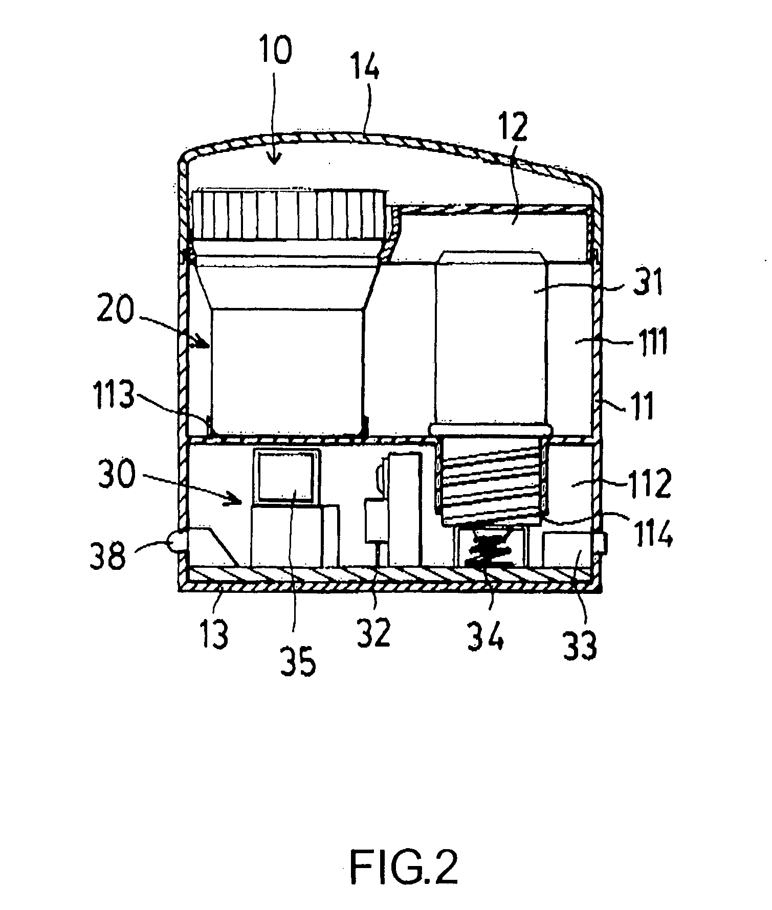
[0016] Referring to FIGS. 1˜2, the invention showing a cleansing unit consists of a body proper (10), a container unit (20), and a motorized unit (30).

[0017] The body proper (10) includes an outer shell (11), an inner lid (12), a base (13), and an outer lid (14). The outer shell (11) is divided into an upper compartment (111) and a lower compartment (112). On the bottom of the upper compartment (111) is a position fixing ring (113) and a positioning hole (114) to connect to the lower compartment (112) through a hollow tube (115). On top of the hollow tube (115) is a first through hole (116). The inner lid (12) is affixed to the upper compartment (111) and matching the outer shell (11) is the position fixing ring (113) for the frame (121) to correspond to the first through hole (116) and a second through hole (122) of the hollow tube (...


PUM


Abstract

A contact lens cleansing unit and consists of a body proper, a container unit, and a motorized unit. The body proper includes an outer shell, an inner lid, a base, and an outer lid. The outer shell is divided into an upper and a lower compartment in between which is a positioning hole. The inner lid is placed on the upper compartment having a frame for the container unit. The container unit has a sensor and a lens rack is placed within the frame on the upper compartment. The motorized unit contains the UV light affixed to the positioning hole of the upper compartment while a circuit board is placed in the lower compartment. The invention is able to achieve total cleaning and disinfecting through the combination of UV light and sub-ultrasonic vibrations plus ease of maintenance should the UV light bulb become defective.

Description

BACKGROUND OF THE INVENTION [0001] (a) Field of the Invention [0002] The invention relates to a contact lenses cleansing unit using low-frequency, sub-ultrasonic vibrations for cleaning and disinfecting to protect contact lenses from damages. By the opening and closing actions of a lid, switching on and off is achieved for safety. [0003] (b) Description of the Prior Art [0004] According to U.S. Pat. No. 5,144,144, the corresponding “contact lens cleaning / disinfecting system” consists of an upper cover and a lower base to form a motorized unit. The upper cover has a UV light while the lower base includes a cleaning / disinfecting chamber for saline, a supporting rod, a current generator, and an electronic control for the UV light and the current generator. The supporting rod is a pair of a lower rod for the lenses and a higher rod for prevention of UV radiation. The current generator is a magnetic pad fastened to the end of a spring and rotated to generate current to remove microbes, t...

Claims


Application Information

Patent Timeline
IPC IPC(8): A61L12/02A61L12/06B08B3/12B08B7/00
CPCA61L12/026B08B7/0057B08B3/12A61L12/063
Inventor LAI, JUNG-HUA
Owner LAI JUNG HUA
Why Eureka
Try Eureka