Roofmatestm roofing accessories

Inactive Publication Date: 2005-02-10
ROOFMATES
View PDF9 Cites 12 Cited by
  • Summary
  • Abstract
  • Description
  • Claims
  • Application Information

AI Technical Summary

Benefits of technology

[0055] Another embodiment of the present invention, SHINGLESAW™, comprises a pneumatically powered miniaturized reciprocating saw designed especially for roofing applications. In an alternative embodiment, SHINGLESAW™ may be powered by rechargeable battery packs or the like. SHINGLESAW™ is the size and shape of a Prior Art razor knife, but is powered and provided with a depth gauge to prevent cutting through roofing underlayment or the like.
[00

Problems solved by technology

An alarming number of construction site accidents are due to falls from pitched roofs by workmen, or injuries sustained by workmen when roofing materials (shingles, felt, nails, flashing, compounds, sealants, and the like) or tools (hammer, nail guns, water jugs, and the like) fall from a roof onto workers or passersby below.
One of the basic difficulties in roof work is transporting the materials up to the roof and storing them there until needed.
Thus, large quantities of shingles, tiles, slates, or the like, may need to be stored on the roof prior to installation.
If a fellow workman or passerby is below when such a large amount of material falls, serious injury or even death can occur.
In addition, although probably less hazardous, workers and passersby below are also in danger of serious injury from falling tools, hammers, and smaller amounts of roofing materials and the like.
In addition to causing stress on the body, such a work environment is inefficient, as such long reaches increase the time needed to install shingles and more readily fatigue the roofer.
Moreover, extended reaches may put the roofer at increase risk of falling due to loss of balance and the like.
Roofing materials and tools may be more likely to fall off a roof if a roofer has to stretch to reach them.
Such a primitive technique, commonly used, provides very little purchase for the roofer or materials to rest upon.
In addition, it may take time at the jobsite for the roofer to secure such scrap lumber, cut it to size, measure for nail spacing, and install.
However, most, if not all, of these attempts have failed in one or more ways, and none of these patented invention appear to have been commercially successful or readily available in the marketplace.
Most of these schemes utilize unnecessarily complicated apparatus, which is too costly for the average roofer to afford, to heavy to lift to the jobsite, and to cumbersome to work with.
The problem with the Eisenmenger system is that it requires that a ladder with specialized fittings first be hauled up to the roof and secured before the platform can be installed.
However, it appears that Bitner is limited to a device for supporting a walk-board or plank, and does not explicitly provide support for ladders, tools, supplies, or roofing materials.
In addition, the Bitner device utilizes a fairly complex and expensive screw-jack leveling system to provide infinite

Method used


Image

  • Roofmatestm roofing accessories
  • Roofmatestm roofing accessories
  • Roofmatestm roofing accessories

Examples


Example

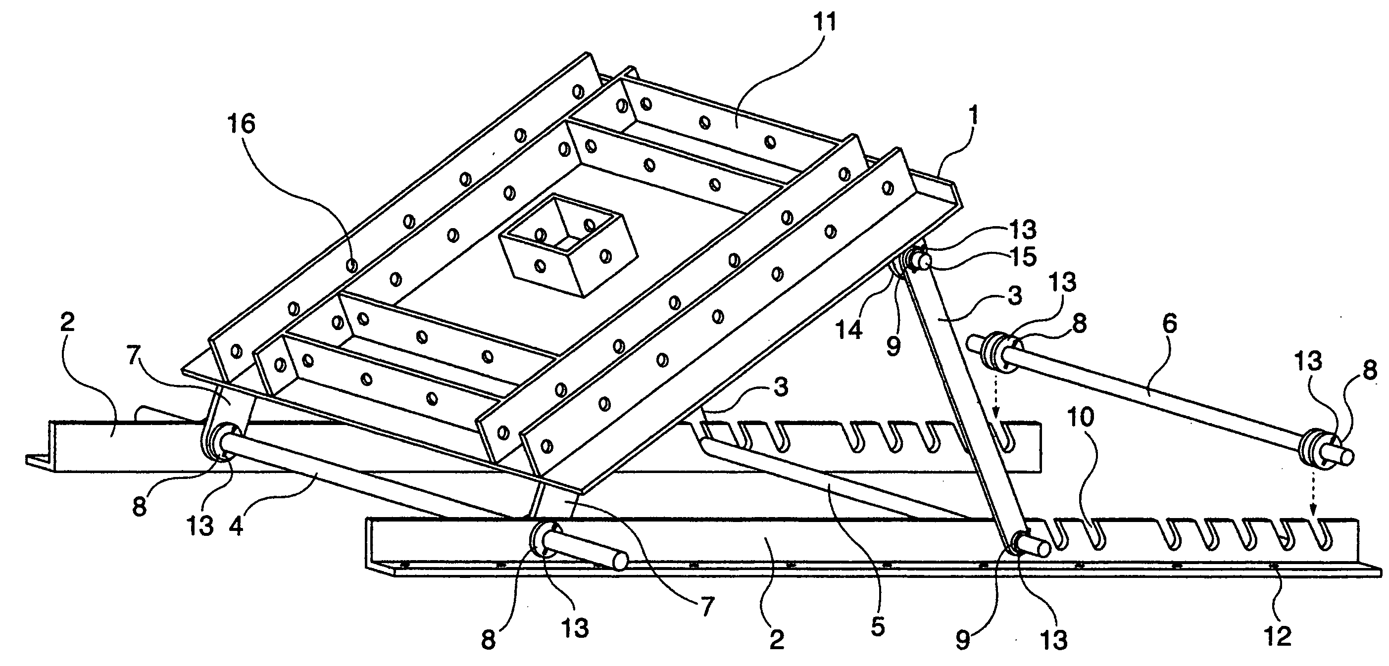
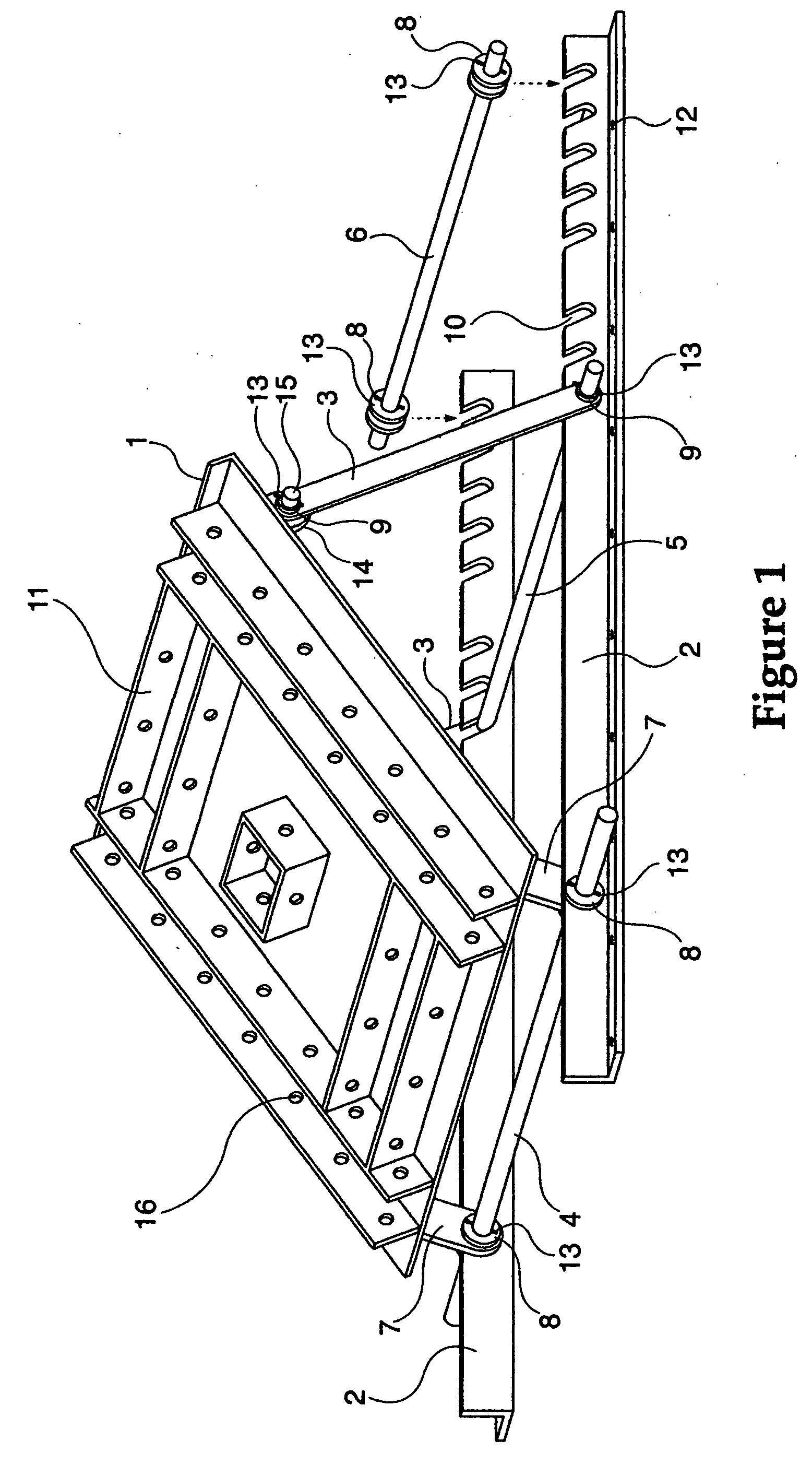
[0163]FIG. 1 is a perspective view of the ladder and scaffold support of the first embodiment of the present invention. Main support table 1 for the unit may support a ladder, siding jack, walking board, or the like and may be constructed from aluminum sheet of approximately ¼ inch in thickness. Support adjustment plates 11 may be provided from aluminum angle stock or flat plate welded to support table 1. In the alternative, support table 1 and adjustment plates 11 may be constructed from a single piece of cast aluminum.

[0164] Materials other than aluminum may be used, of course. However, for high strength and low weight, the inventor has found aluminum construction to work well. The apparatus of the present invention could be conceivably made of other metals (e.g., steel) or even from plastics or composites (e.g., fiberglass and / or carbon fiber construction) without departing from the spirit and scope of the present invention.

[0165] Pre-drilled holes 16 may be provided in support...

Example

[0196]FIG. 13 is a side view of the material and supply support of the second embodiment of the present invention, illustrating how the angle of main support table 1 may be changed. The location and spacing of notches 10 is set to correspond to typical and popular roof pitches, and may allow adjustment from pitches from 4 / 12 to 12 / 12.

[0197]FIG. 14 is a top perspective view of the material and supply support of the second embodiment of the present invention, providing another illustration of the apparatus. It should be noted that the particular arrangement of the lip on main support table 1 is by way of example only. Other configurations may be provided without departing from the spirit and scope of the present invention.

[0198]FIG. 15 is a bottom view of the material and supply support of the second embodiment of the present invention. FIG. 16 is another side view of the material and supply support of the second embodiment of the present invention, as installed on a roof.

[0199]FIG...

Example

[0213]FIG. 27 is a perspective view of the material and supply tray of the third embodiment of the present invention. In the third embodiment of the present invention, which may be marketed under the name UTILITYMATE™, a trademark of the inventor, a tool tray 271 is provided which may be backed with a layer of foam 272 to prevent the tray from slipping off the roof, while allowing the tray to be freely moved along and up and down the roof, as work progresses.

[0214] The tool tray may comprise a flat lower portion backed with a layer of medium density expanded polyurethane foam 272, the type commonly sold for upholstery in upholstery and fabric shops, although other types of foam or elastic material may be used without departing from the spirit and scope of the present invention. A number of compartments with or without dividers 273 may be provided in the tray for holding nails, shingles, tubes of roofing compound, tools, and the like.

[0215] Lower compartments may be divided by divi...


PUM

PropertyMeasurementUnit
Angleaaaaaaaaaa
Sizeaaaaaaaaaa
Densityaaaaaaaaaa

Abstract

A number of roofing accessories, including a lightweight adjustable ladder and scaffold support are disclosed. The scaffold support is provided with a pair of rails spaced the standard spacing of most roof joists. Connected to the rails through suitable holes and slots, are rods supporting an adjustable platform. One of the rods may be placed through a corresponding slot to achieve a suitable angle of adjustment corresponding to roof incline. An apparatus is also provided for supporting loads of materials or supplies on an inclined roof, using components and parts in common with the scaffold support, or components and parts similar thereto. A tool tray is provided which may be backed with a layer of foam to prevent the tray from slipping off the roof, while allowing the tray to be freely moved along and up and down the roof, as work progresses.

Description

CROSS-REFERENCE TO RELATED APPLICATIONS [0001] This application is a Divisional of U.S. patent application Ser. No. 10 / 050,964, filed on Jan. 22, 2002, and incorporated herein by reference in its entirety. [0002] Application Ser. No. 10 / 050,964 in turn claims priority from Provisional U.S. Patent Application No. 60 / 262,650, filed on Jan. 22, 2001, and incorporated herein by reference in its entirety. [0003] application Ser. No. 10 / 050,964 in turn claims priority from Provisional U.S. Patent Application No. 60 / 286,527, filed on Apr. 27, 2001, and incorporated herein by reference in its entirety. [0004] application Ser. No. 10 / 050,964 in turn claims priority from Provisional U.S. Patent Application No. 60 / 297,530, filed on Jun. 13, 2001, and incorporated herein by reference in its entirety. [0005] application Ser. No. 10 / 050,964 in turn claims priority from Provisional U.S. Patent Application No. 60 / 304,098, filed on Jul. 11, 2001, and incorporated herein by reference in its entirety....

Claims


Application Information

Patent Timeline
IPC IPC(8): B23D45/00B23D49/11B23D61/02B23D61/04B23D61/12B23D61/14B27B9/02E04D15/00E04D15/02E06C7/44
CPCB23D45/003B23D49/11B23D61/02B23D61/04B23D61/12E06C7/426B27B9/02E04D15/00E04D15/003E04D15/02B23D61/14E04G3/265
Inventor GARRETT, ROBERT
Owner ROOFMATES
Why Eureka
Try Eureka