Fluid extractor device and kit

Inactive Publication Date: 2018-02-01
SWANSON WAYNE ARTHUR
View PDF6 Cites 0 Cited by
  • Summary
  • Abstract
  • Description
  • Claims
  • Application Information

AI Technical Summary

Benefits of technology

[0018]Therefore it is an aspect of the present invention to provide an inexpensive, easy-to-use device for cleanly removing oil from a used oil filt

Problems solved by technology

Even after draining, however, the old oil filters still hold some remaining oil.
When it does spill it is messy and difficult to clean up.
In particular, in boats, the remaining oil can get into the bilge systems and from there pumped into bodies of water, causing pollution.
In addition, the remaining oil in the oil filters means that the oil filters will require special hazardous material handling before disposal or recycling.
This arrangement has several drawbacks that make it not work ve

Method used


Image

  • Fluid extractor device and kit
  • Fluid extractor device and kit
  • Fluid extractor device and kit

Examples


Embodiment Construction

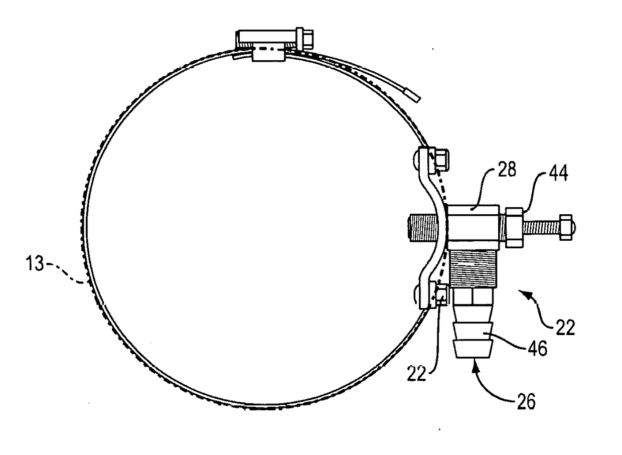
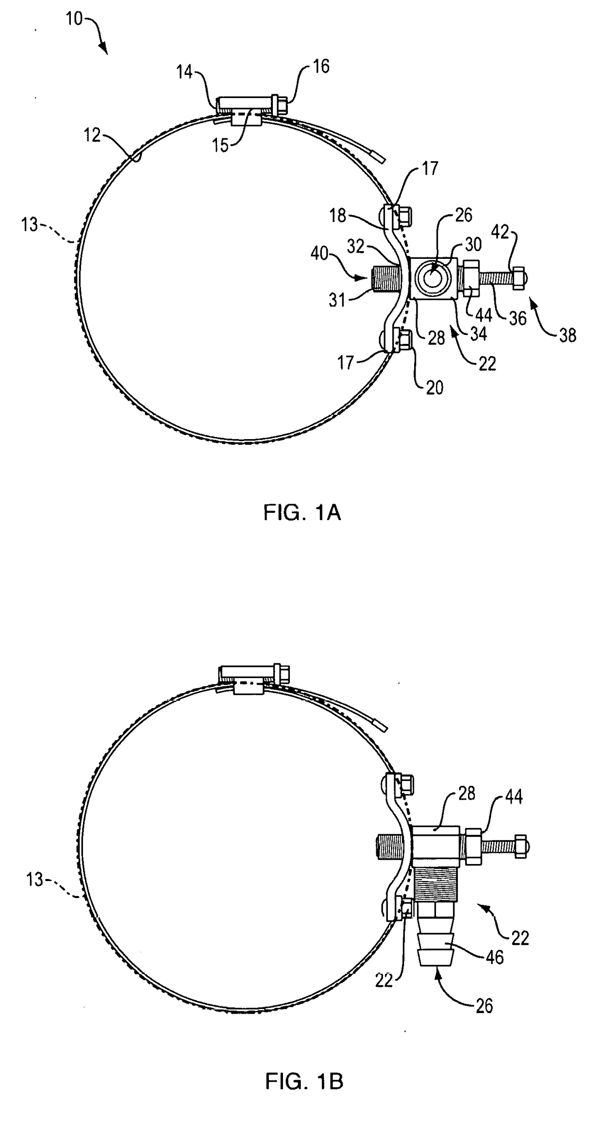
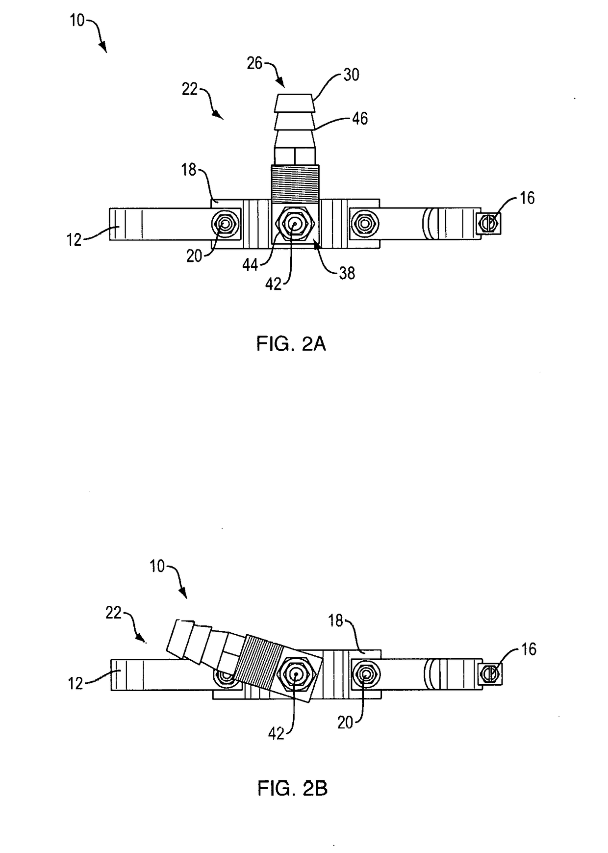
[0051]Referring first to FIGS. 1A and 1B, top down views of fluid extractor device 10 are provided. In each view, we see ring 12 with ring clamp 15 and ring circumference 13; bracket 18; valve 22; and pin 38. Bracket 18 interrupts ring 12 so that bracket 18 is a part of ring circumference 13. Ring 12 is the preferred hose clamp ring. Ring clamp 15 includes the preferred tightening screw 14 and screw head 16. Bracket 18 has bracket screws 20 on either side at ring-bracket affixation points 17. Although bracket screws 20 are the preferred method to affix ring 12 and bracket 18 together, it is understood that ring 12 and bracket 18 may be affixed by any means commonly used in the art, such as welding. Although bracket screws 20 are indicated from the inside of ring 12, it is understood that bracket screws 20 extend through ring 12 and are therefore disposed on both sides of ring 12. Valve 22 has base 28 and vacuum extension 30 perpendicular to base 28. Base 28 has bracket side 32 that ...


PUM

PropertyMeasurementUnit
Widthaaaaaaaaaa
Distanceaaaaaaaaaa
Circumferenceaaaaaaaaaa

Abstract

A fluid extractor device including a ring with a circumference capable of fitting around an oil filter; a bracket affixed to the ring; and a valve including a base attached to the bracket, an extendable pin extending through the base, and a vacuum extension extending perpendicularly from the base and terminating in a vacuum aperture.

Description

CLAIM OF PRIORITY[0001]This application is a continuation in part of co-pending U.S. patent application Ser. No. 14 / 487,531, filed on Sep. 16, 2014, which claims the benefit of priority of U.S. Provisional Patent Application Ser. No. 61 / 879,008, filed on Sep. 17, 2013.FIELD OF THE INVENTION[0002]The present invention relates to fluid extractors and, specifically, to an improved fluid extractor device and systems adapted for removing oil from oil filters.BACKGROUND[0003]Oil filters are used the world over in oil lubrication systems for automobiles, boats, and other motor vehicles. Oil filters are used to filter dirt and other contaminants and / or detritus from the oil used in the oil lubrication systems. Periodically, the oil and oil filters in these systems are changed. The oil is drained from the system and the oil filter is removed and replaced with a new oil filter. Even after draining, however, the old oil filters still hold some remaining oil. The old oil filters therefore must ...

Claims


Application Information

Patent Timeline
IPC IPC(8): B01D35/31B01D35/16
CPCB01D35/16B01D35/31
Inventor SWANSON, WAYNE ARTHUR
Owner SWANSON WAYNE ARTHUR
Why Eureka
Try Eureka