
Method for operating a gas discharge lamp and gas discharge lamp system

A technology for gas discharge lamps and driving gas, which is applied to electric light sources, electrical components, lighting devices, etc., can solve problems such as expensive costs, and achieve the effects of low cost, reduced deviation, and low electric strength

Inactive Publication Date: 2013-01-09
OSRAM GMBH
View PDF5 Cites 0 Cited by
  • Summary
  • Abstract
  • Description
  • Claims
  • Application Information

AI Technical Summary

Problems solved by technology

In this case, for example, the practical feasibility of ignition via a resonant circuit is expensive and cost-intensive for the required ignition voltage, especially due to the high currents in the resonant circuit and the high quality of the components associated therewith and the switching high current loads

Method used


Image

  • Method for operating a gas discharge lamp and gas discharge lamp system
  • Method for operating a gas discharge lamp and gas discharge lamp system
  • Method for operating a gas discharge lamp and gas discharge lamp system

Examples


Embodiment Construction

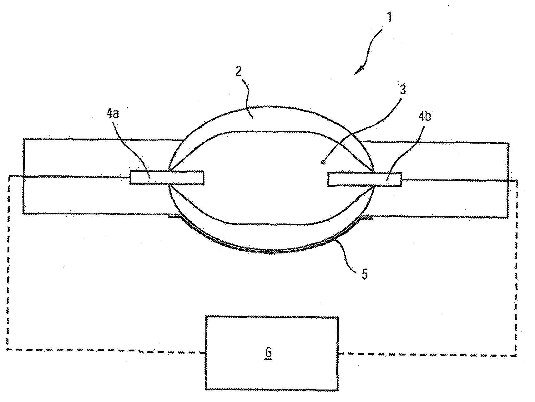
[0028] figure 1 A gas discharge lamp 1 is shown with a discharge vessel 2 in a cavity 3 of which two electrodes 4a, 4b are located and which is filled with a mercury-free vapor filling. Here, a capacitive ignition aid element (“capacitive ignition aid”) 5 is present on the outside of the discharge vessel 2 . The ignition aid 5 forms a capacitance towards each of the electrodes 4a, 4b, which is charged or recharged with each half-wave of the high-frequency alternating voltage. An alternating electric field is thus formed in the cavity 3 , which causes a dielectric barrier discharge of the gas atoms or gas molecules present in the cavity 3 . The discharge generates charge carriers via the electrodes 4a, 4b for completely igniting the gas discharge lamp 1 .

[0029] The ignition aid element 5 can comprise at least one ignition aid layer, an ignition aid wire, a cladding clip, a return wire or the like. The ignition aid 5 can basically form a capacitance with both electrodes 4a...


PUM


Abstract

The invention relates to a method of operating a gas discharge lamp (1), wherein said gas discharge lamp (1) comprises a discharge vessel (2), two electrodes (4a, 4b) protruding into the hollow space (3) of said vessel, and at least one capacitive ignition aid element (5). A DC voltage superimposed with a high frequency AC voltage is applied to the electrodes (4a, 4b) and / or to the at least one capacitive ignition aid element (5) whilst the gas discharge lamp is being ignited.; Said gas discharge lamp system is equipped with at least one gas discharge lamp (1) and a control device (6) for activating the at least one gas discharge lamp (1) which comprises a discharge vessel (2), two electrodes (4a, 4b) protruding into the hollow space (3) of said vessel, also comprising at least one capacitive ignition aid element (5), and the control device (6) is configured such that a DC voltage superimposed with a high frequency AC voltage is applied to the electrodes (4a, 4b) of the respective gas discharge lamps (1).

Description

technical field [0001] The invention relates to a method for operating a gas discharge lamp, wherein the gas discharge lamp has a discharge vessel and at least one ignition aid, into the cavity of which two electrodes protrude, wherein during ignition the A high-frequency alternating voltage is applied to the electrodes. The invention also relates to a gas discharge lamp system with at least one gas discharge lamp and a control device for controlling the at least one gas discharge lamp. Background technique [0002] For mercury-free discharge lamps, pulsed ignition with an ignition parameter of dU / dt>70 kV / μs and a voltage of greater than 20 kV is usually used to ignite the discharge lamp by means of a ballast. Mercury-free discharge lamps with capacitive ignition aids are ignited at an ignition voltage of approximately 16 kV with the described pulse parameters, with practically high variations not only between the lamps but also in the ignition of the individual lamps. ...

Claims


Application Information

Patent Timeline
Patent Type & Authority Applications(China)
IPC IPC(8): H05B41/04H05B41/288
CPCH05B41/288H05B41/04
Inventor 迈克尔·伯尼克
Owner OSRAM GMBH
Learn More