Containers and methods for the on-demand dispensing of flowable materials

a flowable material and container technology, applied in the field of containers, can solve the problems of any flowable material dispensing problem, and achieve the effect of improving the dispensing efficiency and reducing the dispensing difficulty

Inactive Publication Date: 2005-02-10
PBM PLASTICS
View PDF8 Cites 52 Cited by
  • Summary
  • Abstract
  • Description
  • Claims
  • Application Information

AI Technical Summary

Benefits of technology

[0006] Importantly, the container includes a valve system which provides for substantially simultaneous on-demand dispensing of flowable material from the liner through the discharge opening of the cap. The preferred valve system includes one-way discharge and inlet valves. The one-way discharge valves allows only flowable material to be discharged from the liner via the discharge opening, but prevents ambient air from being introduced into the liner when the discharge of flowable material is finished. On the other hand, the one-way inlet valve serves to trap air within the interior space of the container shell to permit the flowable material within the liner to be discharged through the discharge opening in response to a collapsing force applied against the side wall of the container shell. This in turn allows the ingress of ambient air into the interior space when such collapsing force is removed to allow the side wall of the container shell to regain its original shape.

Problems solved by technology

Dispensing problems exist for any flowable material, however, when it only partially fills the interior volume of the container (i.e., which occurs after some of the contents in the container have been dispensed through periodic use).

Method used


Image

  • Containers and methods for the on-demand dispensing of flowable materials
  • Containers and methods for the on-demand dispensing of flowable materials
  • Containers and methods for the on-demand dispensing of flowable materials

Examples


Embodiment Construction

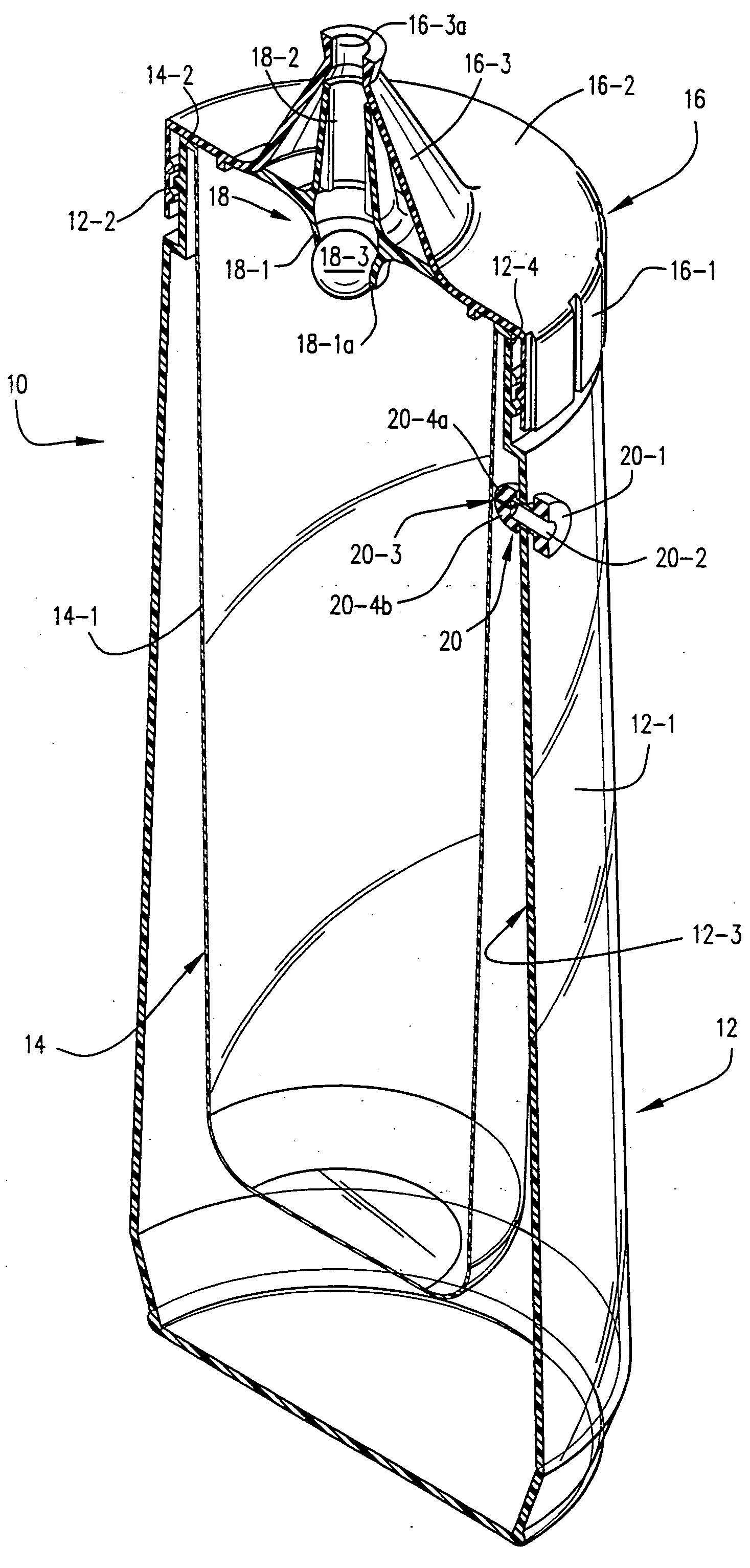
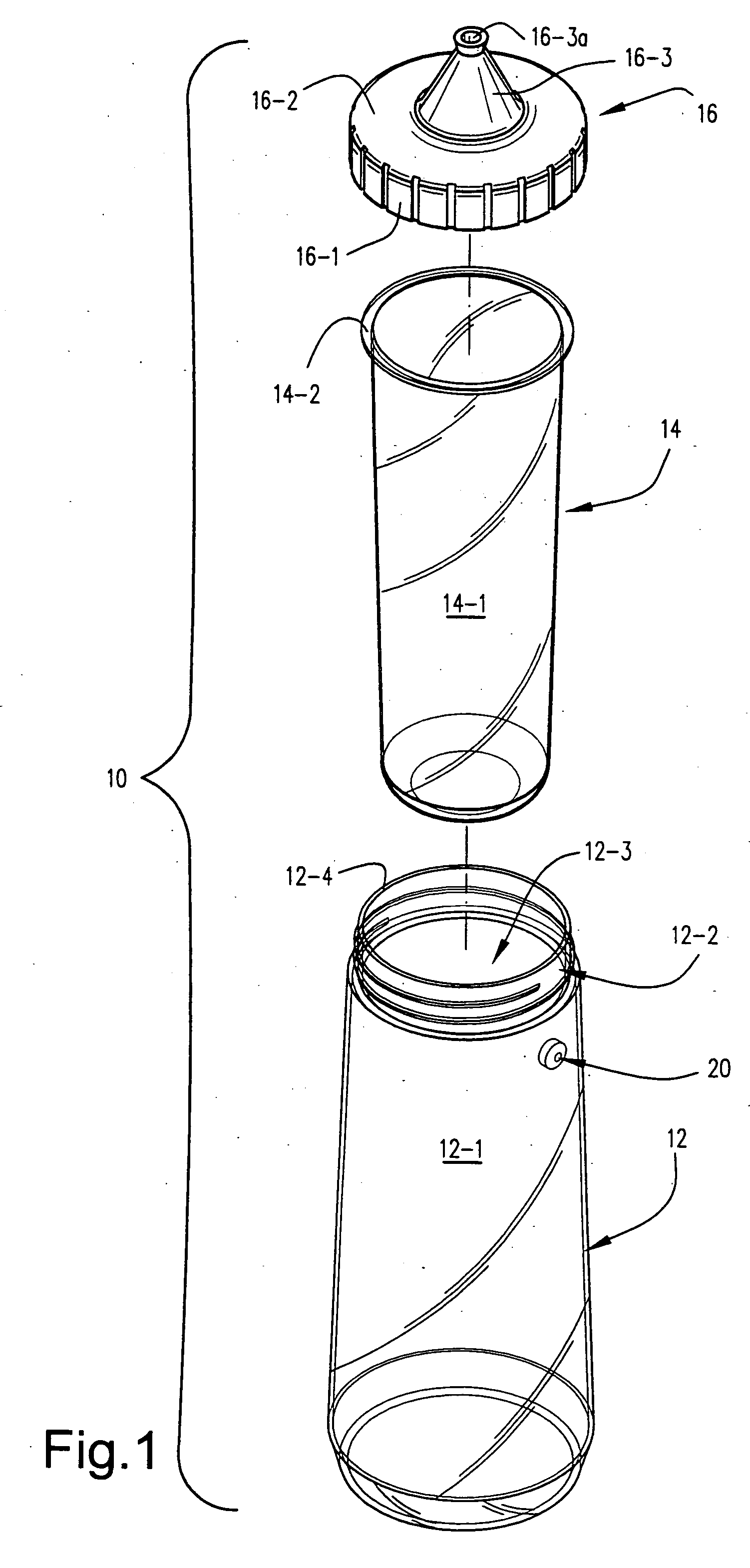
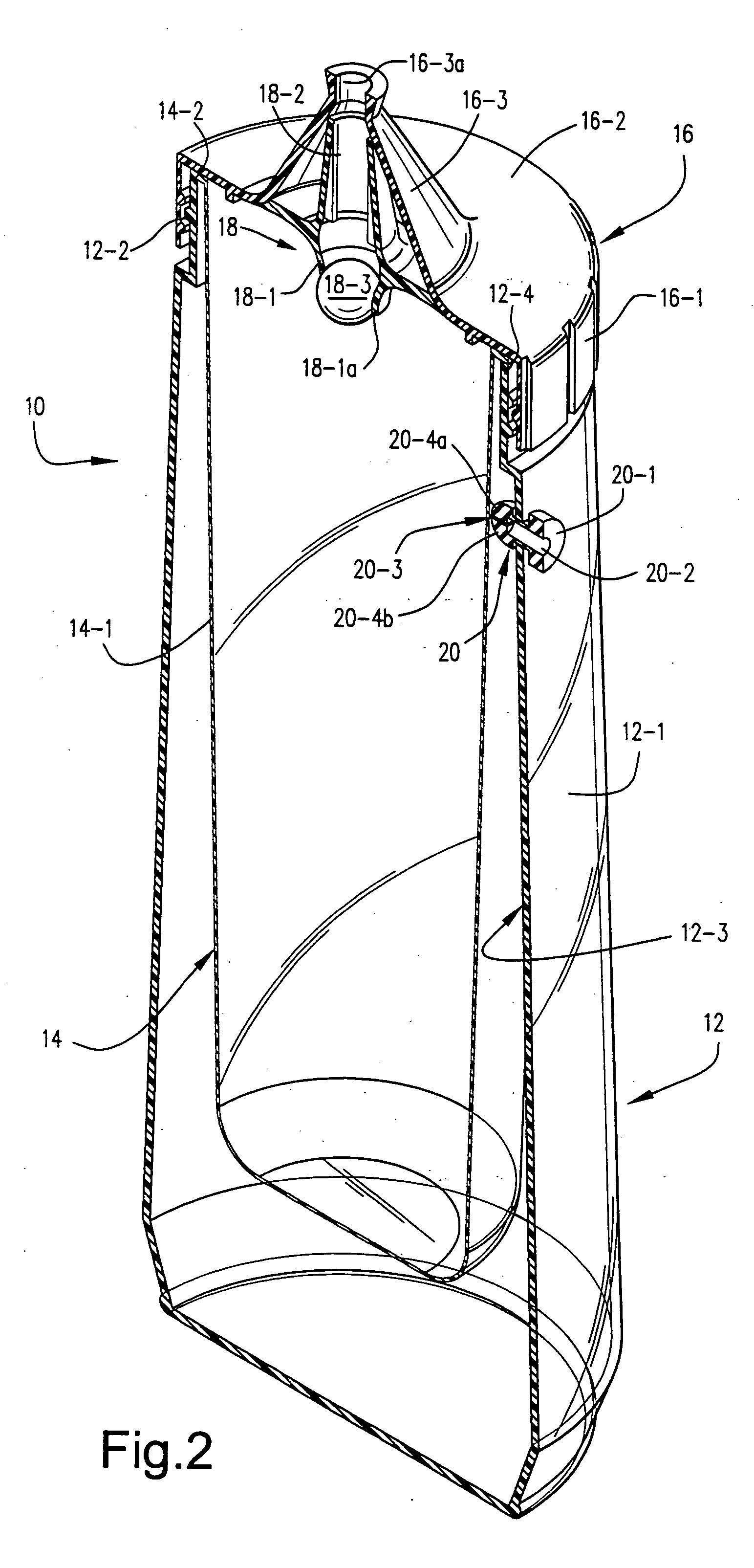
[0012] As shown in accompanying FIG. 1, a particularly preferred embodiment of the present invention includes an open-ended, shape-retaining flexible outer container shell 12, a liner 14 and a dispensing cap 16. The liner 14 unitarily includes a flaccid elongate body portion 14-1 having a closed bottom, and an open-ended top defined by a self-supporting and shape-retaining annular flange member 14-2. Most preferably, the flexible liner 14 is one that is described more fully in U.S. Pat. Nos. 4,836,764 and 5,091,231, the entire content of each being incorporated hereinto by reference.

[0013] By the term “self-supporting” is meant that the structure is capable of supporting its own weight against gravity without deformation. Thus, the flaccid body portion 14-1 is non-self-supporting since it is incapable of supporting its own weight against gravity. The term “shape retaining” means that the structure is capable of retaining and / or resiliently returning to its original shape after the ...


PUM


Abstract

Containers and methods are disclosed whereby portions of an available stand-by supply of flowable material within a container may be dispensed substantially immediately on-demand. Preferably, the containers include an open-ended container shell having a resilient, shape-retaining side wall defining an interior space, a liner positioned within the interior space of the container shell, and a cap closing the open-ended container shell to seal the liner against leakage of flowable material. The liner has a flaccid liner body for containing a flowable material to be dispensed. The cap has a discharge opening to allow an amount of flowable material to be discharged therethrough from the liner body. Importantly, the container includes a valve system which includes one-way discharge and inlet valves. The one-way discharge valve allows only flowable material to be discharged from the liner via the discharge opening, but prevents ambient air from being introduced into the liner when the discharge of flowable material is finished. The one-way inlet valve serves to trap air within the interior space of the container shell in response to a collapsing force applied against the side wall of the container shell which, in turn, allows ambient air to enter the interior space when such collapsing force is removed.

Description

FIELD OF THE INVENTION [0001] The present invention relates generally to the field of containers employed to dispense flowable materials. In particularly preferred forms, the invention is embodied dispensing containers which allow on-demand dispensing of flowable materials contained therewithin and thereby ensure that substantially all such flowable materials are available and capable of being used. BACKGROUND AND SUMMARY OF THE INVENTION [0002] A variety of flowable materials (e.g., liquids, gases. gels, powders, slurries and the like) are sometimes desired to be dispensed in portions from containers for their intended use. For example, certain food condiments (e.g., mustard, ketchup, mayonnaise and the like) are typically contained in a so-called squeeze bottle which enables them to be applied onto food in desired amounts through an outlet opening. When squeezed, therefore, the condiment will be forcibly urged through the outlet opening and onto the food. [0003] Dispensing problem...

Claims


Application Information

Patent Timeline
Patent Type & Authority Applications(United States)
IPC IPC(8): G01F11/00G01F11/08
CPCG01F11/082
Inventor GAY, RANDOLPH G. IIIBURKE, ADAM P.
Owner PBM PLASTICS
Why Eureka
Try Eureka