Conveying arrangement for sheet quires and method for combining sheet quires

a technology of conveying arrangement and sheet quires, which is applied in the direction of conveying parts, article feeders, article separation, etc., can solve the problems of reducing the speed, and reducing the speed of sheets or sheet quires, so as to achieve fast and careful process guidance, the speed difference between the fed-in sheet quires and the overlapping sheet quires can be noticeably higher, and the speed speed is slower

Inactive Publication Date: 2005-02-10
WILL-PEMCO
View PDF6 Cites 7 Cited by
  • Summary
  • Abstract
  • Description
  • Claims
  • Application Information

AI Technical Summary

Benefits of technology

[0007] In contrast to the known methods and arrangements described above, it is an object of the present invention to provide a conveying arrangement which makes it possible to convey sheets that are cut from webs or sorted sheets at very high speed.
[0008] It is furthermore an object of the present invention to reduce the high conveying speed over a relatively short movement distance to a speed suitable for depositing and, in the process, prevent the sheets or sheet quires from being damaged.

Problems solved by technology

Given such high speeds, it is difficult to deposit the sheet quires in a gathering area without damaging them.
The speed of the sheets or sheet quires must be reduced drastically for the depositing, since an orderly deposit of the sheet quires is otherwise not possible.
Until now, several production stages were successively connected to reduce the speed in case of high speed differences, which involved considerable structural expenditure.
However, an arrangement of this type cannot be used if several sheets are stacked one above the other, in so-called sheet quires or paper quires.
A machine or method of this type and an arrangement of this type, however, is less suitable for use with sensitive paper sheets and very high speeds, since it can result in damage to the sheets or sheet quires.

Method used


Image

  • Conveying arrangement for sheet quires and method for combining sheet quires
  • Conveying arrangement for sheet quires and method for combining sheet quires
  • Conveying arrangement for sheet quires and method for combining sheet quires

Examples


Embodiment Construction

[0026] In the following figures, the same elements are provided with the same reference numbers, so that these will not be presented again.

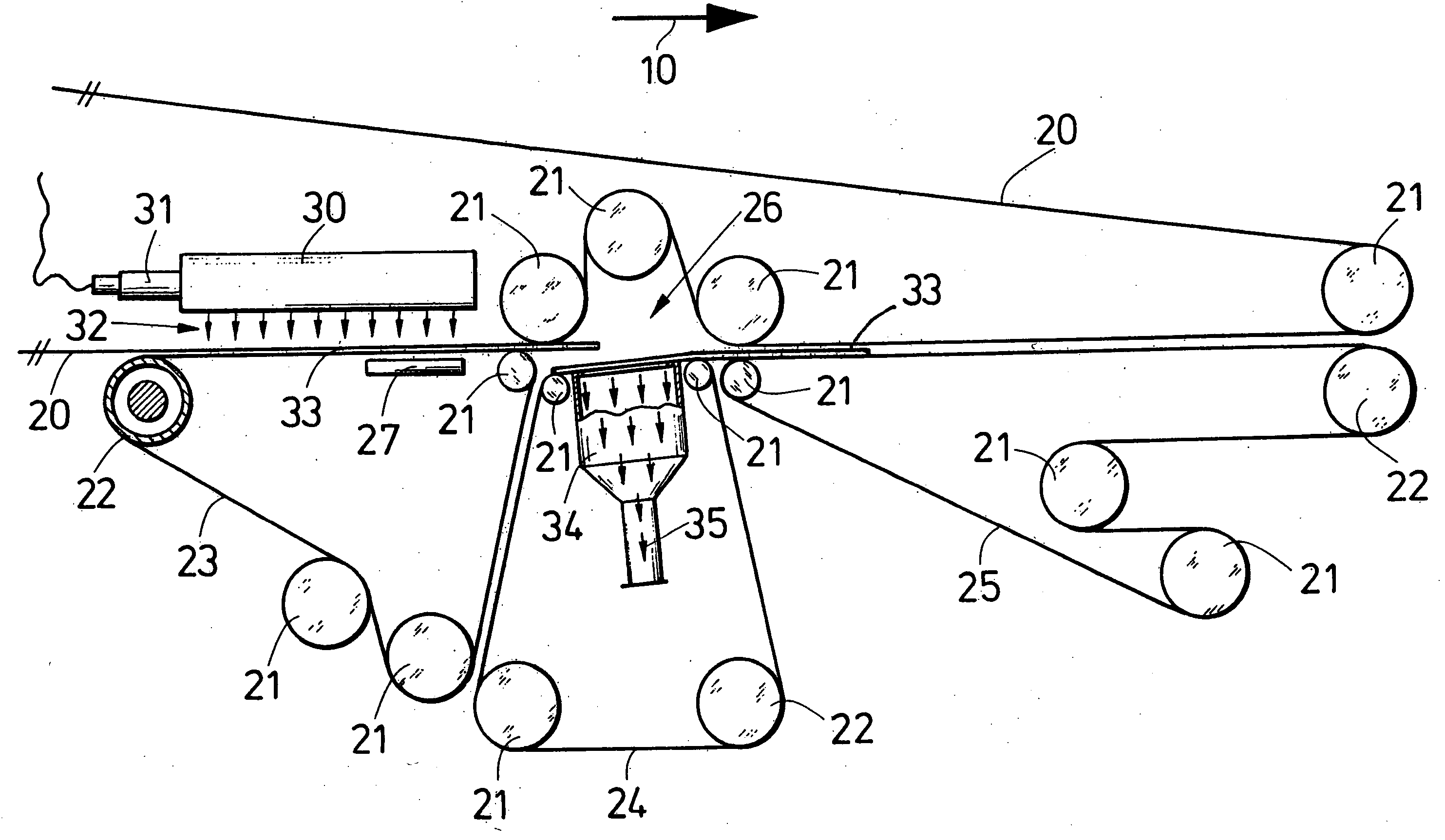
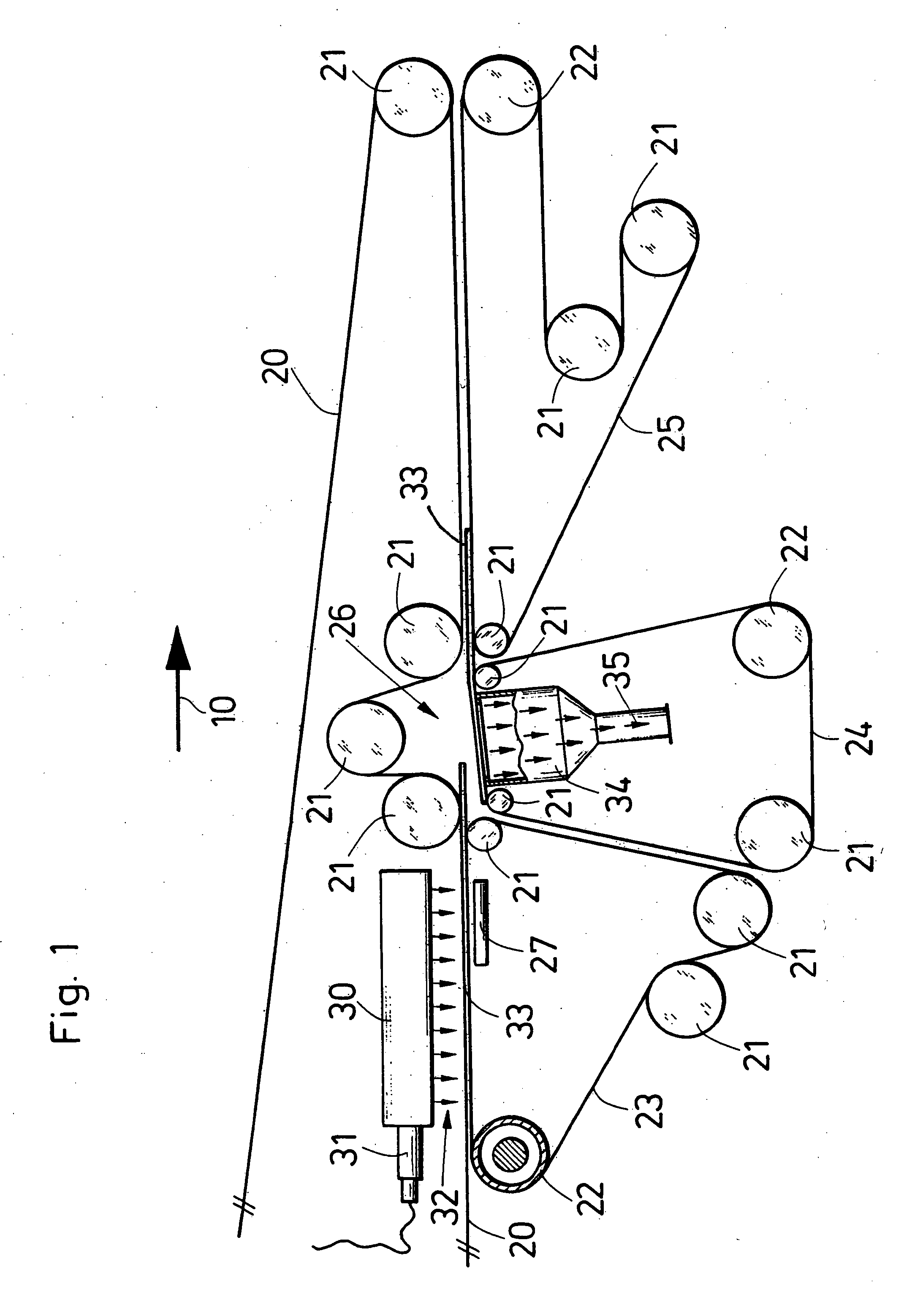
[0027]FIG. 1 shows a view from the side of the essential parts of a conveying arrangement according to the invention.

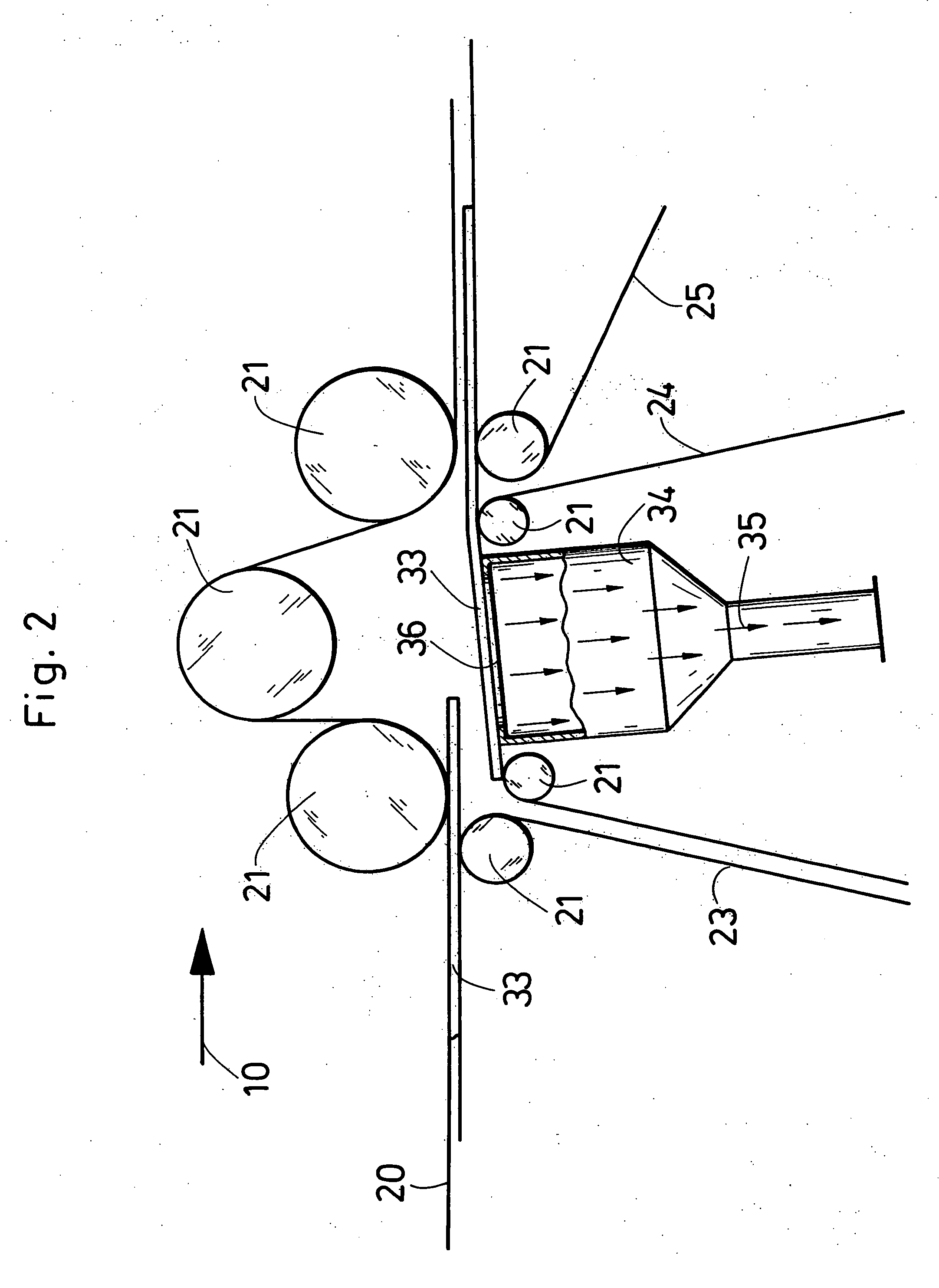
[0028] Paper quires 33, held between a top belt 20 and a conveying belt 23, are transported in a conveying direction 10 toward a deceleration belt 24. The top belt 20 is deflected with deflection rollers 21 and is driven by means of a drive roller or drive unit, not shown in FIG. 1. The conveying belt 23 is deflected in the same way via deflection rollers 21 and is driven via a drive roller 22. The same is true for the deceleration belt 24 and a lower belt 25.

[0029] The paper quires consisting of several paper sheets, for example 4 to 7 sheets, are electrically charged by an ionization device 30 provided with an electrical connection 31 and the electrostatic field 32 generated with it. The paper sheets in the respective paper qu...


PUM

PropertyMeasurementUnit
speedaaaaaaaaaa
areaaaaaaaaaaa
suctionaaaaaaaaaa

Abstract

A conveying arrangement for sheet quires includes successively arranged conveying devices of which a downstream conveying device as seen in a conveying direction has a lower speed than an upstream conveying device and at least one ionization device for electrostatic charging of the sheet quires. The downstream conveying device includes a suction device for administering suction air to the sheet quires at stationary suction openings.

Description

CROSS-REFERENCE TO RELATED APPLICATION [0001] This application is a divisional of application Ser. No. 10 / 166,737, filed Jun. 12, 2002, and claims the priority of German Patent Application No. 101 28 653.8 filed in Germany on Jun. 15, 2001. The disclosure of the above applications and the disclosures of each and every U.S. and foreign patent and patent application mentioned herein, are incorporated herein by reference.BACKGROUND OF THE INVENTION [0002] The invention relates to an arrangement for conveying sheet quires, in particular supplied to at least one gathering area. Such an arrangement comprises at least two successively arranged conveying devices, wherein the front conveying device, in the conveying direction, has a lower speed than the one in the rear. The arrangement also includes at least one ionization device for the electrostatic charging of the sheet quires. The invention furthermore relates a method for joining the sheet quires. [0003] Conveying arrangements of the ab...

Claims


Application Information

Patent Timeline
Patent Type & Authority Applications(United States)
IPC IPC(8): B65H5/02B65G47/31B65H5/00B65H5/22B65H5/24B65H29/66
CPCB65H29/6627B65H2406/32B65H2406/30B65H2301/5132
Inventor HAGEMANN, GUNTHERHERPEL, FRANKPETER, JURGEN
Owner WILL-PEMCO
Why Eureka
Try Eureka