Barrow for moving observation

a moving observation and barrow technology, applied in the direction of measuring wheels, instruments, optical radiation measurement, etc., can solve the problems of difficult to carry out quick and accurate moving observation, and achieve the effect of easy carrying out, quick and accurate moving observation, and reduced workload of operators

Inactive Publication Date: 2005-02-10
NAGOYA UNIVERSITY
View PDF13 Cites 17 Cited by
  • Summary
  • Abstract
  • Description
  • Claims
  • Application Information

AI Technical Summary

Benefits of technology

[0008] Therefore, according to the barrow of this invention, there is no need for setting and identifying the position and the orientation of the equipment as a preliminary work with respect to each observation like the conventional observation, so that a quick and accurate moving observation can easily carry out in the field such as a forest area, a construction field, an archaeological site and a disaster site.
[0009] In the barrow of this invention, this barrow preferably comprises an acceleration sensor which detects the acceleration of the barrow that directed to the mutually orthogonal three axes and, the observation position and direction calculating device uses an information of self-contained navigation from the acceleration sensor to calculate the position and the zenithal angle and the azimuthal angle of the direction of the observation of the equipment. Thereby, the acceleration sensor detects the accelerations of the barrow in the directions of the mutually orthogonal three axes which these axes are extended along such as the longitudinal direction, the transversal direction and the up-and-down direction of the barrow respectively, and the observation position and direction calculating sensor also uses these accelerations to calculate the position the equipment and the zenithal angle and the azimuthal angle of the direction of the observation of the equipment, so that an error in the calculation of the position of the equipment will be able to reduce when an acceleration from any impact or the like occurs on the barrow.
[0010] Additionally, in the barrow of this invention, it is preferable that observation position and direction calculating device comprises a moving pathway calculation unit which continuously calculate the position of said equipment and calculate a moving pathway of the barrow in accordance with the transition of the position of the equipment and moving pathway display unit that indicates the calculated said moving pathway on a screen. Thereby, an observation operator in moving observation and a researcher who analyzes observation data in afterward can check the moving pathway of the barrow in the moving observation on the screen, so that the operator always can check the current position to prevent the risk of distress and the researcher will be able to carry out a detailed analysis of the data in reference to another data such as land features together.
[0011] Moreover, in the barrow of this invention, the barrow preferably comprises one or more auxiliary wheel that regulates the inclination over the predetermined limit of the barrow about said travel surface. Thereby, the inclination of the barrow about the longitudinal direction can parallelize that of the travel surface about the longitudinal direction of the barrow, so a workload of the operator can be reduced during the operator moves the barrow by hand gilding.
[0012] Furthermore, in the barrow of this invention, it is preferable that the observation equipment is at least one of the devices selected from three-dimensional scanner of the laser plane range-finding method, light wave distance meter, photoenvironment measurement device and digital still camera. Thereby, an observation such as a photoenvironment in the forest area can easily carry out.
[0013] Moreover, according to the measurement method of this invention, a quick and accurate moving observation can easily carry out in the field such as a forest area, a construction field, an archaeological site and a disaster site.

Problems solved by technology

However, as described above, setting the observation equipment and identifying the position and the orientation of the equipment as the preliminary works with respect to each observation are time-consuming and troublesome, so there is a problem that a quick and accurate moving observation is difficult to carry out.

Method used


Image

  • Barrow for moving observation
  • Barrow for moving observation
  • Barrow for moving observation

Examples


Embodiment Construction

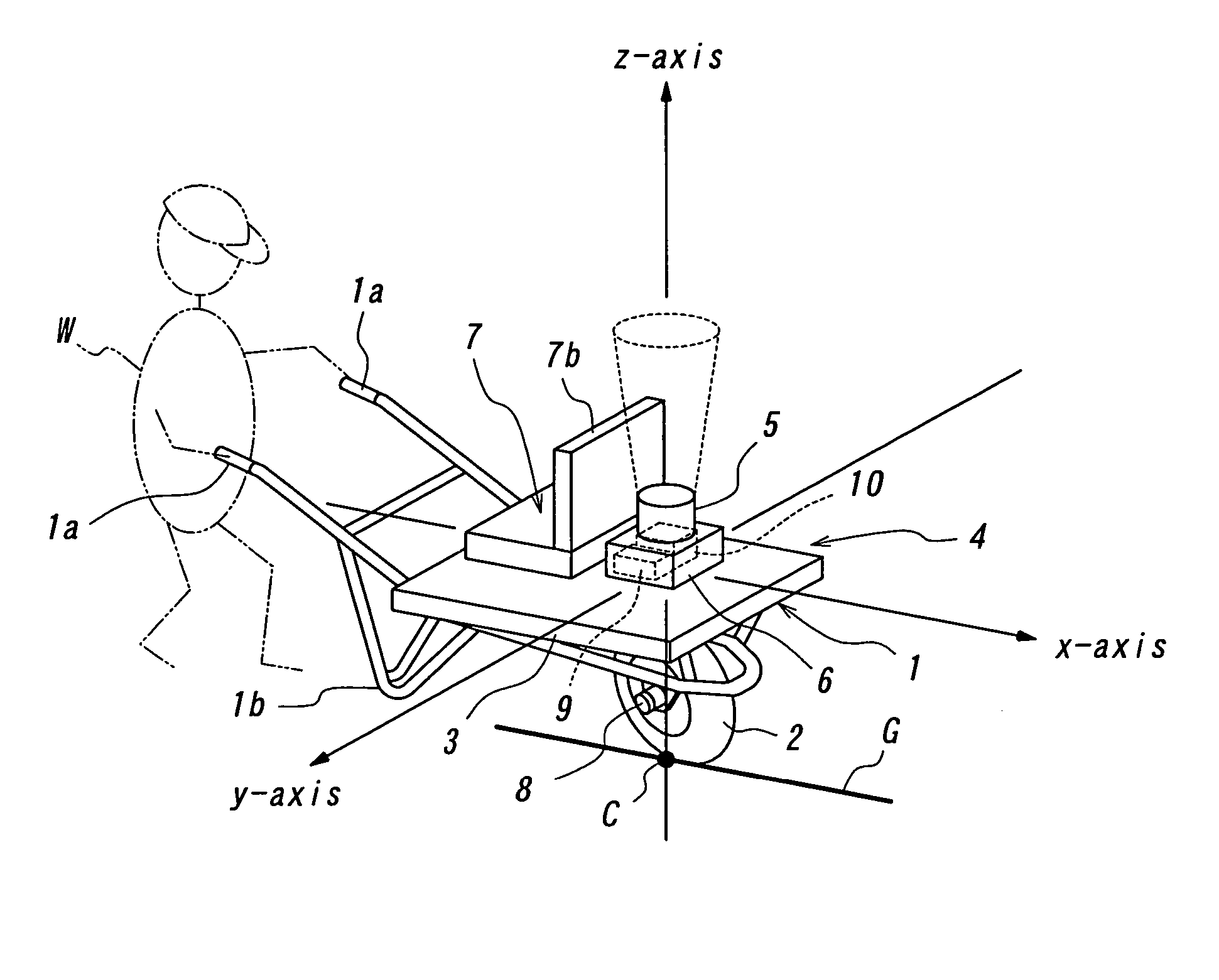
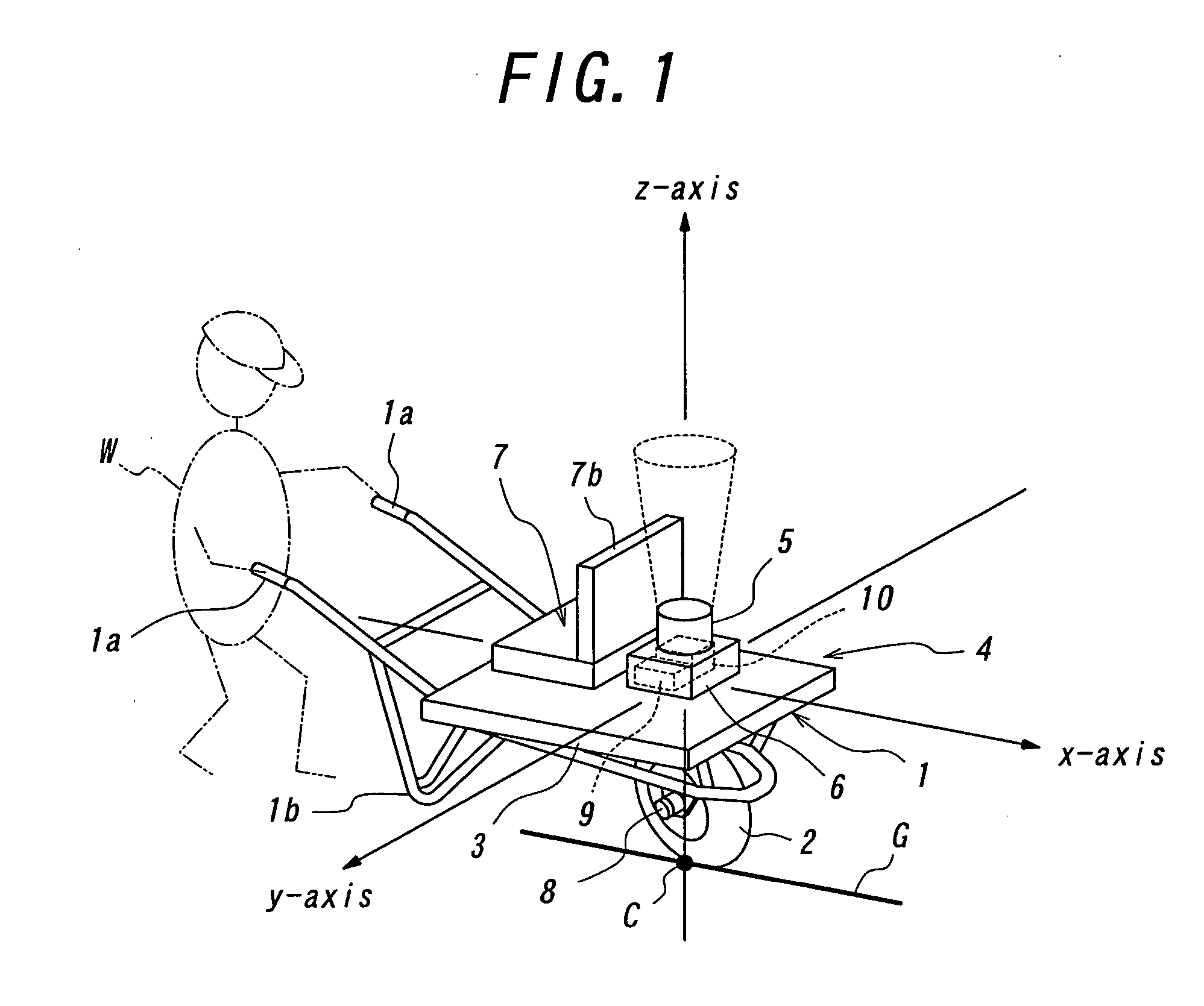
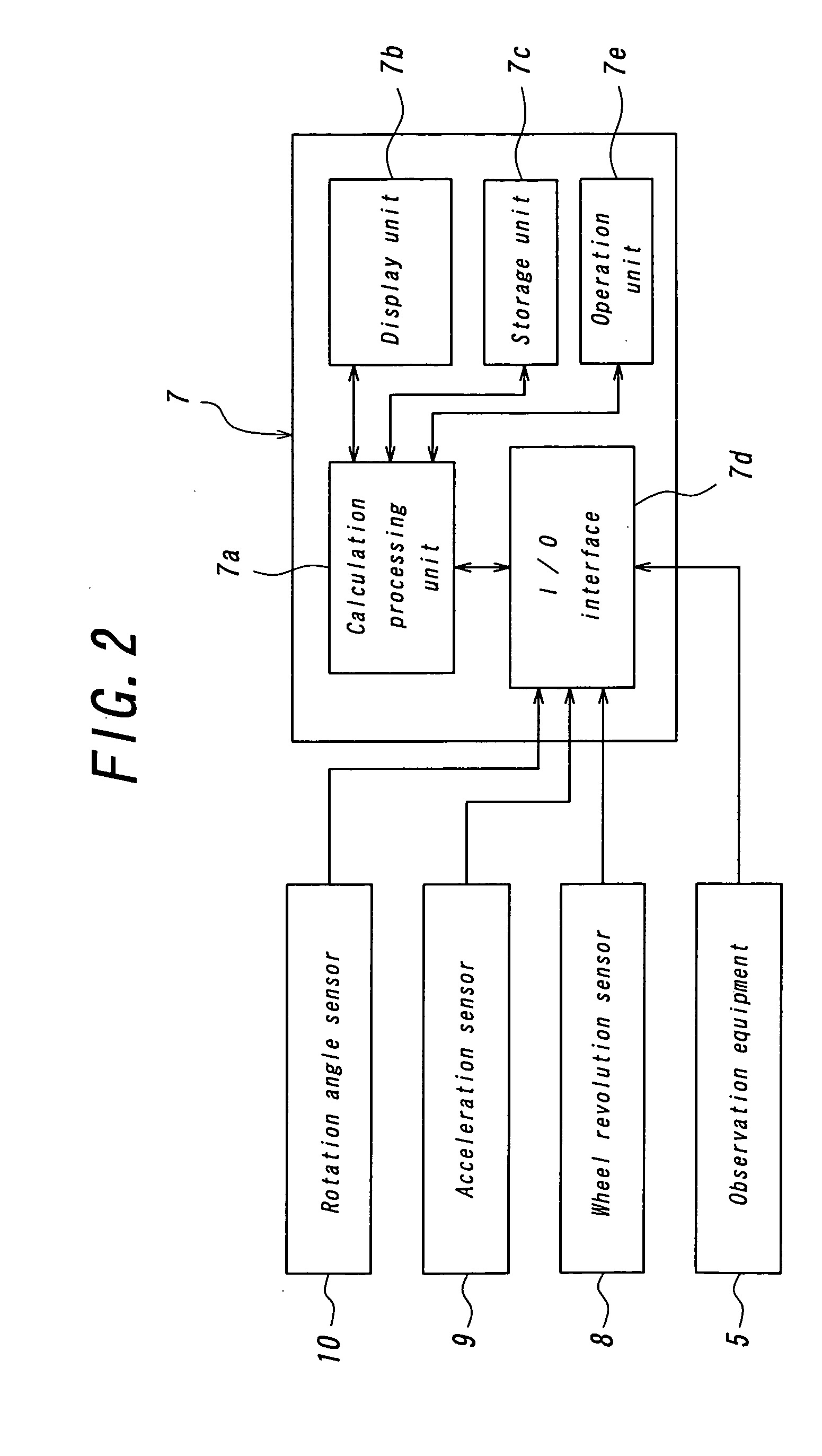
[0016] The embodiment according to this invention will be explained, by way of example, with reference to the accompanying drawings, in which FIG. 1 is schematically perspective view of the appearance of the one embodiment of the barrow for moving observation of this invention and FIG. 2 is a block diagram of the composition of the equipment that is mounted on the barrow of this embodiment.

[0017] As shown in FIG. 1, the barrow for moving observation of this embodiment comprises a dolly 4 which has a frame 1 with a handle for hand gilding and two stems for stay (there only shows one of the stems in the drawing), a wheel 2 which is rotatably supported around the axis at the underneath of frame 1 and a top plate 3 which is mounted on the frame 1, this dolly 4 is driven by hand gilding drive of a observation operator W and by means of the wheel 2 which contact on the grounding point C of the ground level G as the driving surface. The dolly 4 further comprises an observation equipment 5...


PUM


Abstract

This invention relates to a barrow for moving observation which observation equipment 5 is mounted and is driven by one wheel that contacts with a travel surface comprising an acceleration sensor 9 which detects the rotation angles around the mutually orthogonal x, y and z axes, a rotation angle sensor 10 which detects the rotation angles around the mutually orthogonal x, y and z axes, a wheel revolution sensor 8 which detects the revolution of the wheel, a computer 7 that calculate a position and a zenithal angle and a azimuthal angle of the direction of the observation of said equipment 5 in accordance with an information of self-contained navigation from said acceleration sensor 9 and said rotation angle sensor 10 and an information of moving distance from said wheel revolution sensor 8 at least in the observation by said equipment 5.

Description

BACKGROUND OF THE INVENTION [0001] 1. Field of the Invention [0002] The present invention relates to a barrow for moving observation that is suitable for moving observation in the field such as a forest area, a construction field, an archaeological site and a disaster site where radio wave of global positioning system (GPS) is hard to reach. [0003] 2. Description of Related Art [0004] Generally, when an observation of such as photoenvironment will carry out in the field such as the forest area, the construction field, the archaeological site and the disaster site where the radio wave of GPS is hard to reach, before the observation, preliminary works must be made, that is, select a relatively flat area and place the observation equipment on the observation area, identify the observation position by such as celestial observation and triangulation, and identify the zenithal angle and the azimuthal angle of the orientation for the observation of the equipment at the observation area. [0...

Claims


Application Information

Patent Timeline
Patent Type & Authority Applications(United States)
IPC IPC(8): B62B1/00B62B1/22G01B11/25G01C21/12G01C21/16G01J1/00
CPCB62B1/002G01C21/12B62B1/22G01B3/12
Inventor TANAKA, TAKAFUMI
Owner NAGOYA UNIVERSITY
Why Eureka
Try Eureka