Image recording apparatus and method for determining defective image-recording elements

a technology of image recording apparatus and image, applied in the direction of printing, other printing apparatus, etc., can solve the problems of degrading the quality of the recorded image, ejection defects, and defective droplet deposition positions, and achieve the effect of optimal compensation

Inactive Publication Date: 2005-02-10
FUJIFILM CORP
View PDF9 Cites 37 Cited by
  • Summary
  • Abstract
  • Description
  • Claims
  • Application Information

AI Technical Summary

Benefits of technology

The present invention has been implemented taking into account the above described circumstances, and an object thereof is to provide an image-recording device that can accurately determine a defective image-recording element with recording defects and the condition thereof, and a method of determining a defective image-recording element thereof.
In another aspect of the present invention, feedback control is added to modify the subsequent compensation contents by means of at least the previous historical information, so that even if the compensation were to be inaccurate in the previous compensation processing, the same error compensation can be prevented from being performed in the subsequent processing step, and optimal compensation can be performed.

Problems solved by technology

There are cases in which some of the nozzles of the large number of nozzles no longer eject ink for some reason, the amount of ink ejected (the dot size resulting from the ejection of a droplet on the recording paper) and the droplet deposition positions become defective (defective flight direction, non-uniform nozzle positions), and other ejection defects occur.
The presence of such defective nozzles causes the quality of the recorded image to be degraded, thus countermeasures thereto are required.
Moreover, there are drawbacks in a simple pattern in that the results are affected by errors in the measurement positions and that it is difficult to determine defective nozzles.
Furthermore, there is a drawback in that the results are affected by variability in the output of the line sensor for reading the test pattern.
In the case of the method (2) for measuring an actual print job, the actual print job, which is the measurement object, is usually an intricate image, so that there are drawbacks in that it becomes difficult to determine whether image defects are due to a defective nozzle or to the original image content, and to accurately determine a defective nozzle, due to the effect of errors in the measurement positions.
More specifically, dots on the recording paper are read with photoelectric transducing elements arranged with the same pitch as the pitch of the nozzles of the recording head to detect a non-ejection of ink; however, in this method, when the image has a high density, the sensor output difference with the surroundings is smaller, so that defective ink-droplet ejection cannot be accurately determined by comparing individual dots.
In particular, in the case of high-density nozzles used for high resolution image recording, the observation area of each pixel of the line sensor is greater than the nozzle pitch, so that it becomes even more difficult to determine a defective ejection nozzle when the conveyance errors of recording paper and the like are also taken into consideration.
Moreover, the method (3) for measuring the characteristics during ejection inside the head can accurately determine a defective nozzle; however, there is a drawback in that it is difficult to ascertain the degree of deficiency.

Method used


Image

  • Image recording apparatus and method for determining defective image-recording elements
  • Image recording apparatus and method for determining defective image-recording elements
  • Image recording apparatus and method for determining defective image-recording elements

Examples


Embodiment Construction

General Configuration of an Inkjet Recording Apparatus

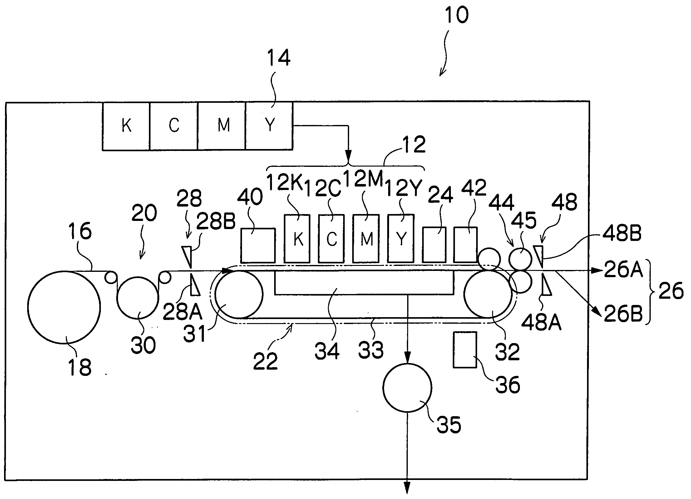
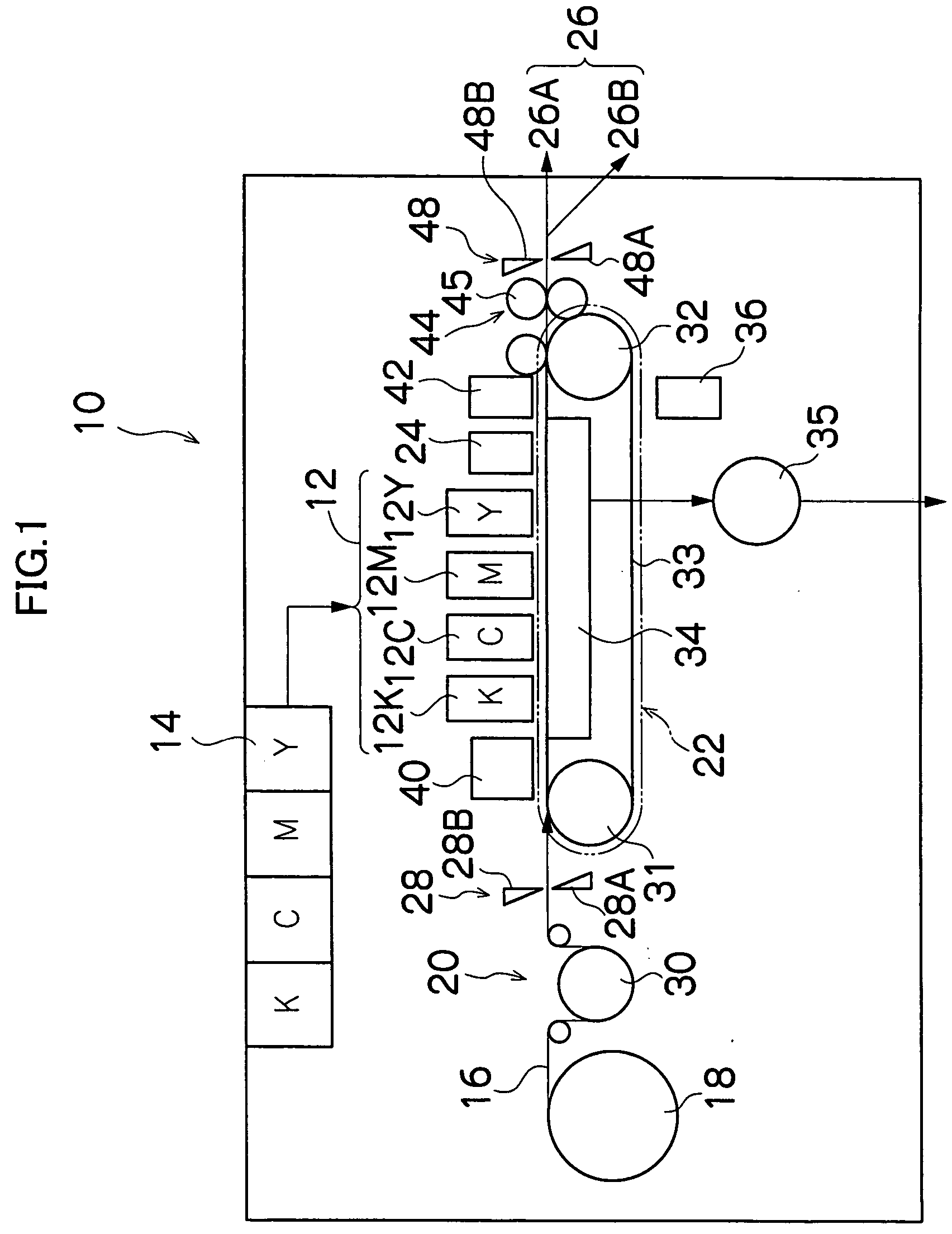
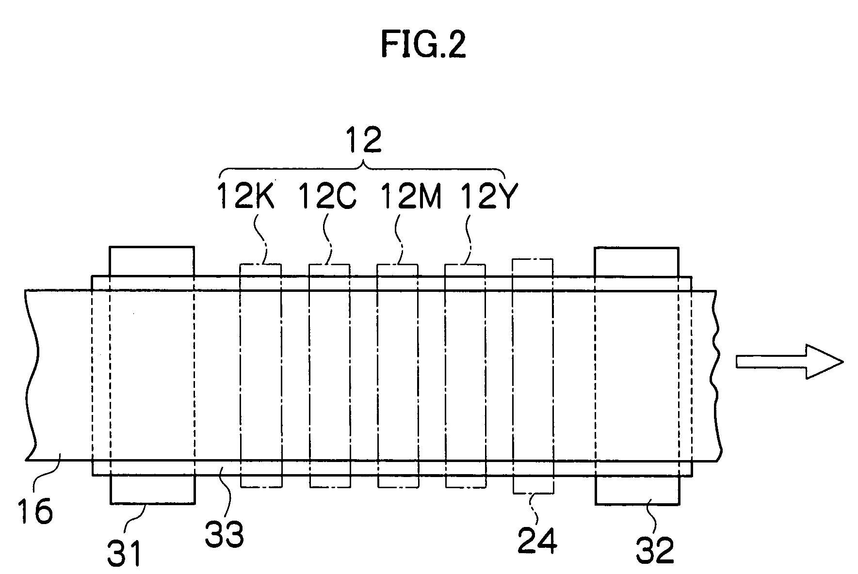
FIG. 1 is a general schematic drawing of an inkjet recording apparatus according to an embodiment of the present invention. As shown in FIG. 1, the inkjet recording apparatus 10 comprises: a printing unit 12 having a plurality of print heads 12K, 12C, 12M, and 12Y for ink colors of black (K), cyan (C), magenta (M), and yellow (Y), respectively; an ink storing / loading unit 14 for storing inks to be supplied to the print heads 12K, 12C, 12M, and 12Y; a paper supply unit 18 for supplying recording paper 16; a decurling unit 20 for removing curl in the recording paper 16; a suction belt conveyance unit 22 disposed facing the nozzle face (ink-droplet ejection face) of the print unit 12, for conveying the recording paper 16 while keeping the recording paper 16 flat; a print determination unit 24 for reading the printed result produced by the printing unit 12; and a paper output unit 26 for outputting image-printed recording paper (pr...


PUM


Abstract

The image recording apparatus comprises: a printing device which includes a full-line recording head having a plurality of image-recording elements arranged along a length corresponding to an entire width of a printing medium, the recording head recording an image on the printing medium by the plurality of image-recording elements; a conveying device which moves at least one of the recording head and the printing medium relatively to each other in a conveyance direction substantially perpendicular to a width direction of the printing medium; an image reading device which includes a plurality of sensors outputting actual sensor output data by reading the image recorded on the printing medium, the plurality of sensors being arranged along the length corresponding to the entire width of the printing medium; and a defective image-recording element determining device which determines a defective one of the plurality of image-recording elements by performing computation for each sensor of the plurality of sensors according to the actual sensor output data obtained from the each sensor, the actual sensor output data obtained from one of the plurality of sensors adjacent to the each sensor, and expected sensor output data expected from the image to be normally recorded.

Description

BACKGROUND OF THE INVENTION 1. Field of the Invention The present invention relates to an image recording apparatus and method, and more particularly to an image recording apparatus and method for determining recording defects of an image-recording element in an inkjet recording apparatus or other image recording apparatus for recording images on a printing medium by a recording head having a plurality of image-recording elements, and to a technique for compensating for recording defects thereof. 2. Description of the Related Art Inkjet recording apparatuses have an inkjet head (print head) in which a large number of nozzles are arranged, and images are formed on recording paper by ejecting ink droplets from the nozzles while moving the print head and the paper relatively to each other. There are cases in which some of the nozzles of the large number of nozzles no longer eject ink for some reason, the amount of ink ejected (the dot size resulting from the ejection of a droplet o...

Claims


Application Information

Patent Timeline
Patent Type & Authority Applications(United States)
IPC IPC(8): B41J2/165B41J2/175
CPCB41J2/16579B41J2/175B41J2/2146B41J2002/14459B41J2/17563
Inventor TATSUMI, SETSUJI
Owner FUJIFILM CORP
Why Eureka
Try Eureka