Identification of laterally positioned servo bands employing differentiating characteristics of servo patterns

Inactive Publication Date: 2005-02-10
IBM CORP
View PDF21 Cites 17 Cited by
  • Summary
  • Abstract
  • Description
  • Claims
  • Application Information

AI Technical Summary

Benefits of technology

[0007] The present invention comprises, in one embodiment, a linear data storage tape having servo information comprising a plurality of separate servo bands of patterns of detectable transitions positioned longitudinally along the linear data storage tape, at least one of which detectable transitions is non-parallel to another detectable transition in the pattern, and the separate servo bands positioned laterally across the linear data storage tape; and the patterns of the separate servo bands are laterally aligned, and at least one of the patterns of a separate servo band having at least one differentiating characteristic with respect to at least one of the laterally aligned patterns of another of the separate servo bands. The differentiating characteristic allows identification of the separate servo bands.
[0014] In a further embodiment, if lateral alignment of the separate patterns is not necessary, and the patterns comprise at least one gap between the non-parallel detectable transitions; and the separate servo bands are positioned laterally across the linear data storage tape; at least one of the patterns of a separate servo band has variations in the gap of the pattern with respect to at least one of the patterns of another of the separate servo bands. For example, where the detectable transitions of a pattern are arranged with at least one of the detectable transitions in one orientation, and at least one detectable transition in a non-parallel orientation with respect to the one orientation, having a first gap therebetween, and the patterns comprise at least a second gap between the pattern and a sequentially adjacent pattern; and wherein the variations in the gap of the patterns of the separate servo bands comprises an expanded one of the first gap and / or the second gap, and a narrowed one of the first gap and / or the second gap. In another example, where the detectable transitions of a pattern are arranged in a first burst of at least one of the detectable transitions in a first azimuthal orientation, a second burst of at least one of the detectable transitions in a second azimuthal orientation, a third burst of at least one of the detectable transitions in the first azimuthal orientation, and a fourth burst of at least one of the detectable transitions in the second azimuthal orientation, and first gaps separating the first and the second bursts and separating the third and the fourth bursts, and second gaps separating the second and the third bursts and separating a sequentially adjacent pattern; and the variations in the gap of the patterns of the separate servo bands comprises an expanded one of a set of the first gaps and a set of the second gaps and narrowed one of a set of the second gaps and a set of the first gaps. This has the same effect as though one of the servo bands was offset laterally a small amount, and added to at one side and truncated at the opposite side, such that the servo system can easily adjust to either band.

Problems solved by technology

Such extra sensors add cost to a tape drive, which is always undesirable, if the extra cost can be avoided.

Method used


Image

  • Identification of laterally positioned servo bands employing differentiating characteristics of servo patterns
  • Identification of laterally positioned servo bands employing differentiating characteristics of servo patterns
  • Identification of laterally positioned servo bands employing differentiating characteristics of servo patterns

Examples


Embodiment Construction

[0035] This invention is described in preferred embodiments in the following description with reference to the Figures, in which like numbers represent the same or similar elements. While this invention is described in terms of the best mode for achieving this invention's objectives, it will be appreciated by those skilled in the art that variations may be accomplished in view of these teachings without deviating from the spirit or scope of the invention.

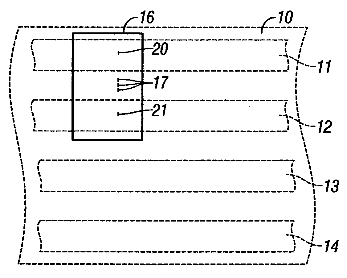
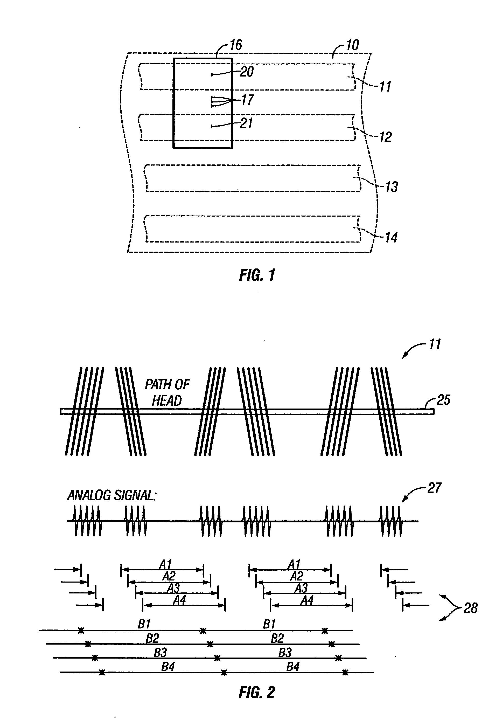
[0036]FIGS. 1 and 2 illustrate a servo system and a linear data storage tape 10, the linear data storage tape having a plurality of separate longitudinal servo bands 11, 12, 13 and 14, which are laterally positioned on the linear data storage tape, and which are identifiable in accordance with the present invention. The example of FIG. 1 comprises a magnetic tape media with magnetically written servo bands, and with data tracks positioned between the servo bands. In magnetic tape media, a tape head 16 typically comprises a number o...


PUM


Abstract

In a tape having separate servo bands of patterns positioned laterally across the tape, the patterns of a separate servo band have at least one differentiating characteristic with respect to patterns of another of the separate servo bands. The differentiating characteristic allows identification of the separate servo bands. For example, the patterns of a separate servo band have differing azimuthal orientations of detectable transitions with respect to another servo band, such as being laterally inverted. In another, variations in the width of gaps of patterns are made with respect to another servo band. In another, variations are made in the number of the detectable transitions of patterns with respect to the patterns of another servo band.

Description

FIELD OF THE INVENTION [0001] This invention relates to separate longitudinal servo bands which are laterally positioned on a linear data storage tape, and, more particularly, to identification of the servo bands for independent addressability. BACKGROUND OF THE INVENTION [0002] Linear data storage tape comprises a medium for storing large amounts of data, and typically comprises a plurality of data tracks that extend longitudinally along the tape. A common example comprises magnetic tape media, and a less common example comprises optical tape media. A tape head is employed for reading and / or writing data on the data tracks, and is typically shared between various data tracks or groups of data tracks, and is moved between tracks or groups of tracks in the lateral direction of the tape. In magnetic tape media, the tape head typically comprises a number of separate elements which read and / or write data with respect to a number of parallel tracks, and is provided with one or more separ...

Claims


Application Information

Patent Timeline
IPC IPC(8): G11B5/008G11B5/584G11B5/78
CPCG11B5/00813G11B5/78G11B5/584
Inventor BUI, NHAN XUANEATON, JAMES HOWARDFUKUDA, JUNICHIJAQUETTE, GLEN ALANOGURA, EIJITAYLOR, MARK ALLANTSURUTA, KAZUHIRO
Owner IBM CORP
Why Eureka
Try Eureka