
Watch with mirror dial plate

a dial plate and dial technology, applied in the field of dial plate watches, can solve the problems of not using a high reflectivity mirror, and none of the above patents disclose the use of a mirror with variable reflectivity controlled electronically, and achieve the effect of easy and efficient manufacture of variable reflectivity

Inactive Publication Date: 2005-02-10
BURNS TOM +1
View PDF5 Cites 2 Cited by
  • Summary
  • Abstract
  • Description
  • Claims
  • Application Information

AI Technical Summary

Benefits of technology

[0014] It is another object of the present invention to provide a new watch with a mirror function, which is controlled electronically for on and off, and variable reflectivity. The watch thus provides mirror and time display.
[0015] A further object of the present invention is to provide a new watch with a mirror function, which may be easily and efficiently manufactured.

Problems solved by technology

None of the above patents disclose a high reflectivity mirror.
Further, none of the above patents discloses the use of a mirror with variable reflectivity controlled electronically.

Method used


Image

  • Watch with mirror dial plate
  • Watch with mirror dial plate
  • Watch with mirror dial plate

Examples


Embodiment Construction

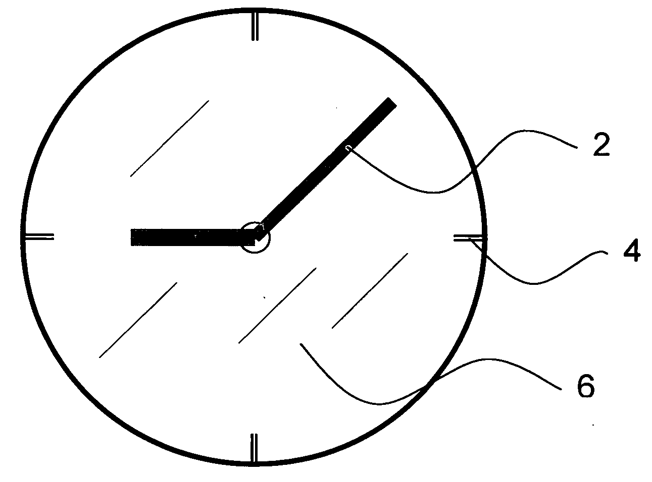
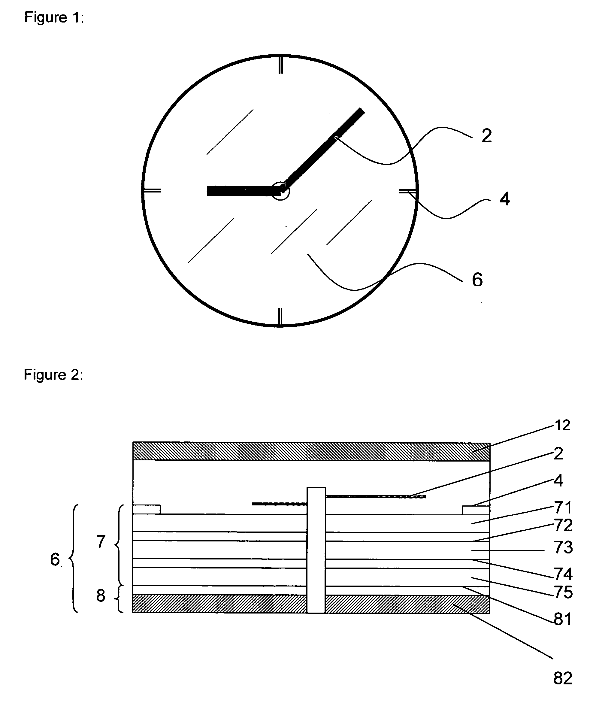
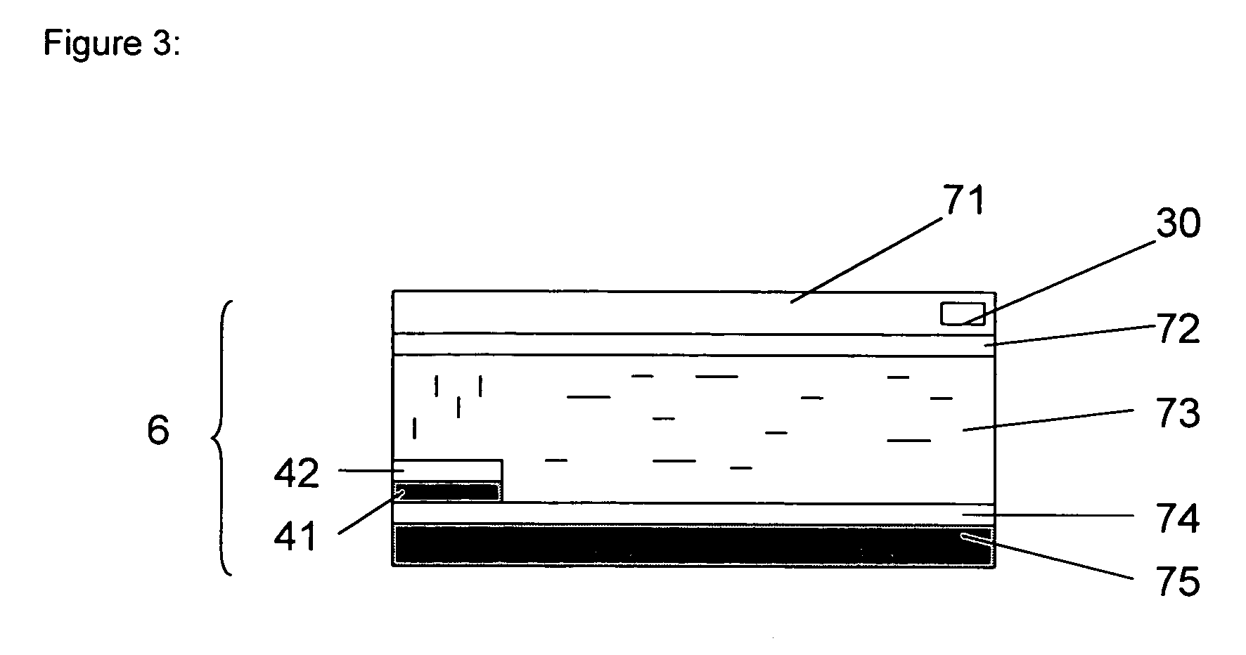
[0022] Referring to FIG. 1, an exemplary watch face having hands 2, dials 4, and a mirror dial plate assembly 6 is showed. The cross sectional view along the lines A-A is showed in FIG. 2. This view serves to illustrate the construction of one embodiment according to the present invention. The watch movement portion omitted in the cross sectional view. A mirror dial plate assembly 6 is placed under the watch crystal 12 and hands 2. The mirror assembly 6 comprises an electronically controllable light valve 7 and a mirror 8. The light valve comprises an electronically controllable media 73 (e.g., liquid crystals) sandwiched between two substrate plates 71 and 75. Both plates are transparent and are each coated with transparent conductive coating 72 and 74 as electrodes to operate the light valve. Under the light valve is the mirror 8 which comprises a mirror coating 81 and a substrate 82. Because a mirror coating is usually also an electrically conductive coating, it is thus preferred...


PUM


Abstract

A watch has a mirror dial plate assembly comprising a light valve layer, and a light reflective layer. The light valve is controlled by an electronic circuit for its on, off, and variable light transmission. The reflectivity of the mirror assembly is thus controlled. Dial marks are incorporated either on or in the light valve layer, or using a separation transparent layer.

Description

CROSS REFERENCE TO RELATED APPLICATIONS [0001] This application claims the benefit of priority from U.S. Provisional Application Ser. No. 60 / 460,445 filed on Apr. 4, 2003. REFERENCE PATENTS [0002][0002] U.S. Pat. No. 4,747,086 [0003] U.S. Pat. No. 6,519,209 [0004] JP Laid Open Publication no. 07-280955BACKGROUND OF THE INVENTION [0005] 1. Field of the Invention [0006] The present invention relates generally to a watch with a dial plate having a mirror function. More specifically, the invention relates to a watch with a dial plate having an electronically controllable mirror. In the normal operating state, the mirror is off. When the mirror is activated, it reflects light so that the user can conveniently use it for makeup or the like. A mirror dial plate with colors or other features incorporated in also presents an attractive watch face. [0007] 2. Description of the Related Art [0008] Watches with various types of mirror functions are known in the prior art. A typical example of su...

Claims


Application Information

Patent Timeline
Patent Type & Authority Applications(United States)
IPC IPC(8): G04C17/00G04G9/00
CPCG04G9/00G04C17/00
Inventor BURNS, TOMQIN, XUZHI
Owner BURNS TOM
Learn More