
Contrast enhancing marking system for application of unobtrusive identification and other markings

Inactive Publication Date: 2005-04-19
SPECTRA SYST CORP
View PDF35 Cites 6 Cited by
  • Summary
  • Abstract
  • Description
  • Claims
  • Application Information

AI Technical Summary

Benefits of technology

[0019]It is an object of this invention to provide an optically contrasting marking system for marking articles having colored, multi-colored or complex backgrounds so as to improve the readability of the marking indicia.
[0022]A method is disclosed for affixing a marking system comprised of an optically contrasting layer on top of a substrate, wherein the optically contrasting layer provides, when stimulated, a uniform background that enhances the process of imaging and / or reading an overlying indicia carrying coded information. The method includes the steps of (a) providing a single article or a plurality of articles, wherein each article has a surface that requires marking (herein referred to as substrate), (b) applying an optically contrasting material (herein referred to as layer) over the substrate, (c) applying another substance over the layer for carrying coded information related in some way to the substrate article (herein referred to as indicia), (d) and with subsequent application of a stimulus, changing the optical characteristics of at least the layer to be in an optically contrasting state so that an optically-based readout technique may reliably detect and decipher the coded information provided by the indicia.
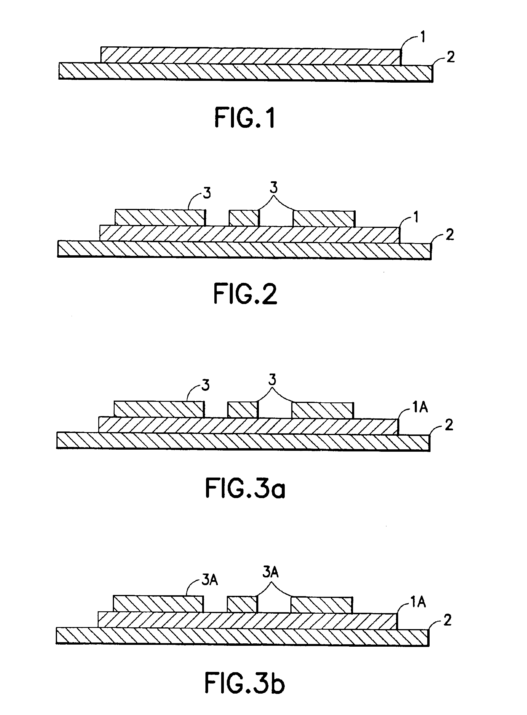
[0028]In one aspect this invention provides a method that includes steps of (a) providing a substrate, upon which (b) an invisible, substantially invisible or otherwise unobtrusive layer of phase change material is applied, the layer changing optically upon the application of an appropriate stimulus, upon which (c) an additional material is applied that carries coded marking information as indicia, which may be (d) optically imaged after or during application of the stimulus to the phase change material for interpretation of the marking information, and (e) preferably, but not necessarily, with subsequent return of the layer to an unobtrusive state. The stimulus causes the phase change material of the layer to assume an optical state that enhances contrast of the layer with the indicia, thereby improving the signal to noise ratio of the system reading the indicia.
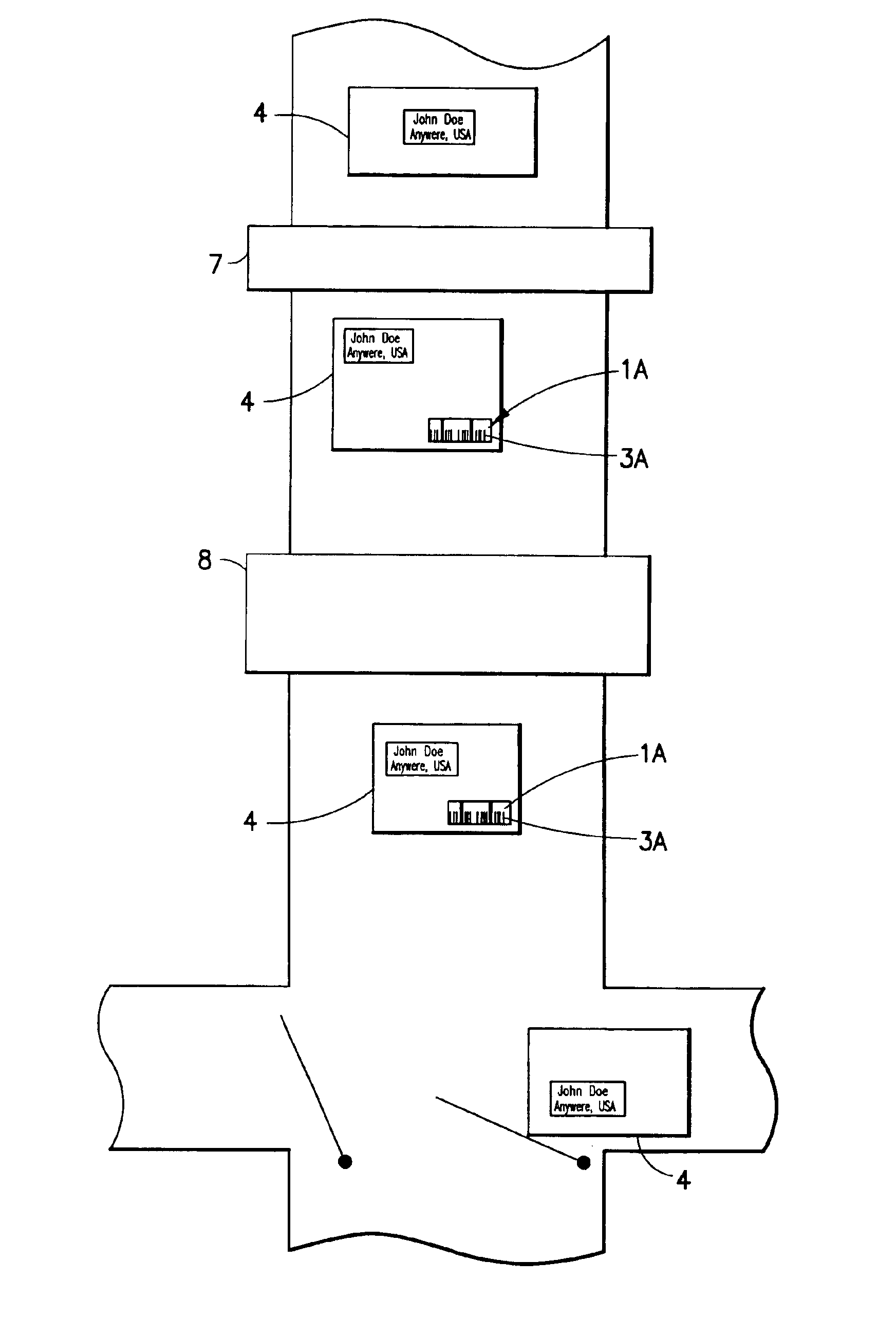
[0029]In accordance with an aspect of this invention a two layer printing technique is employed, where a bottom layer includes a photochromic layer or a thermochromic layer and a top layer contains, in one embodiment, a fluorescent, invisible bar code. The bottom layer is normally invisible. Prior to reading the bar code, the bottom layer is turned from clear to colored by a flash of UV light, or by the application of heat, depending on the nature of the bottom layer (photo- or thermo-chromic.) The color change of the bottom layer serves to obscure the variable reflectivity of the background and provide a uniform reflection beneath the bar code. While the bottom layer remains in the colored state, the invisible, fluorescent bar code is read.
[0031]As an example, assume that the two layer system is disposed upon a multi-colored background, and both the bottom layer and the bar code are transparent. After stimulating the bottom layer, such as by being flashed by a UV light source which turns the photochromic layer from clear to black, or by the application of thermal energy to make the thermochromic layer visible, the overlying bar code can be readily detected by a simple reader.

Problems solved by technology

However, certain situations can render the use of existing technology ineffective.
However, it has been discovered that problems arise when colored, multi-colored or complex backgrounds lie beneath the bar code.
In such instances, the nature of the substrate background typically dampens the signal to noise ratio (SNR) in the bar code imaging equipment, or otherwise causes problems, thus providing incorrect or incomplete information to system operators and / or to automated equipment that relies on a correctly read bar code.
The reduced reliability in the imaging of coded information lying on top of the substrate background typically results from poor contrast between the coded information and the substrate background.
If a bar code or some other computer readable indicia is to be applied to and then read from the mail piece, or the plastic wrapping, then it can be realized that the underlying graphical pattern can significantly interfere with the ability of a bar code scanner mechanism to correctly read the bar code.
While at first glance it might appear that one could simply apply a neutral label to the mail piece, and then place the bar code on the label, this approach would be objectionable for a number of reasons.
First, it adds cost and complexity to the mail piece marking and coding process.
Third, the presence of the label may be visually and aesthetically objectionable when located upon a carefully designed artwork pattern that forms a portion of an advertisement or some other type of message or decoration on the mail piece.
Thus, a method of solving these problems that involves the application of a contrasting label that carries bar code information is problematic, as application of a separate label may obscure important information on the mail piece and / or it may cause other problems.
There exist numerous bar code applications where the appearance of a standard black and white bar code is unacceptable.
However, the difficulty of incorporating these schemes is often increased when the background has variable colors or markings.
This approach is successful for substrates which are uniform in color, but does not solve the problem of a varied background caused by writing or printing beneath the bar code.
This approach, however, is limited by the degree of reflectivity of the background, and also requires a complicated reader system.

Method used


Image

  • Contrast enhancing marking system for application of unobtrusive identification and other markings
  • Contrast enhancing marking system for application of unobtrusive identification and other markings
  • Contrast enhancing marking system for application of unobtrusive identification and other markings

Examples


Embodiment Construction

[0045]This invention employs selected materials to provide for an invisible or unobtrusive marking system wherein a marking does not obscure underlying and / or surrounding information under ambient environmental conditions, while the marking system provides a degree of marking quality necessary to permit use of optical imaging systems for reliable interpretation of the marking.

[0046]It should be realized that the teachings of this invention could be employed to mark and subsequently identify one to many articles. This system can therefore be used in a wide variety of applications ranging from instances where invisible or unobtrusive markings may be read on an infrequent basis, to large scale sorting applications and other similar processes. These teachings are thus not limited for use with mailing systems, but can be applied in a number of different types of application, including as non-limiting examples the marking and sorting of bank checks and the marking and possible sorting of ...


PUM

PropertyMeasurementUnit
Fractionaaaaaaaaaa
Fractionaaaaaaaaaa
Fractionaaaaaaaaaa

Abstract

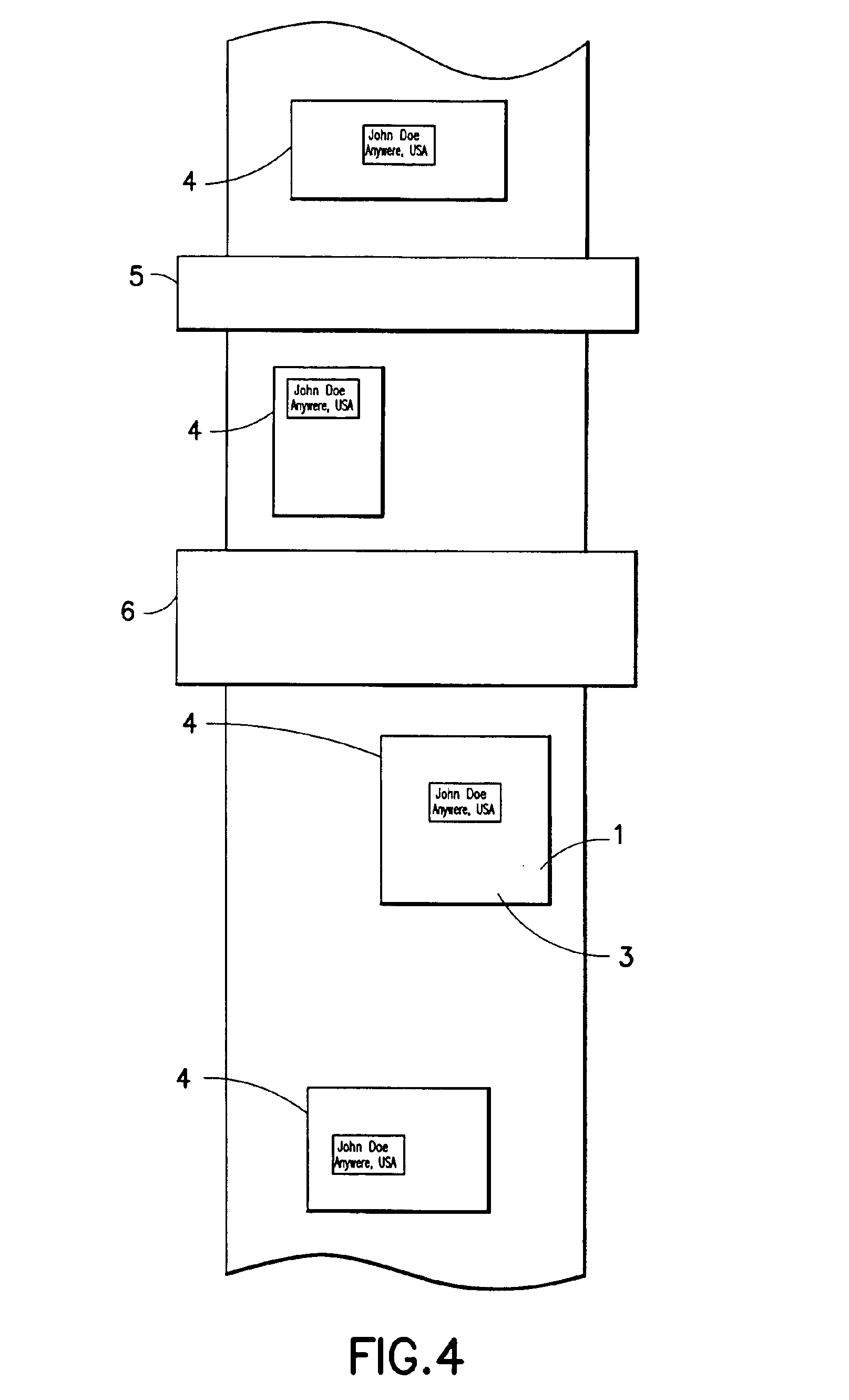
A method and a system is disclosed for affixing invisible or unobtrusive markings to mail pieces (4), and subsequently collecting information from the mail pieces for sorting purposes. The system includes the affixation of an optically contrasting layer (1) to a mail piece, the layer changing optically upon the application of a stimulus to present a contrasting background for imaging encoded information (3) applied over the layer and related to the mail piece.

Description

[0001]Priority is herewith claimed under 35 U.S.C. §119(e) from the following Provision Patent Applications:[0002]ApplicationNo.:Filing DateInventor(s)60 / 265,44031 Jan. 2001Nabil M. Lawandy60 / 265,45831 Jan. 2001Timothy J. Driscoll, Nabil M. Lawandy60 / 270,75422 Feb. 2001Nabil M. Lawandy60 / 270,75522 Feb. 2001Nabil M. Lawandy60 / 276,63116 Mar. 2001Nabil M. Lawandy, Timothy J. Driscoll60 / 278,69026 Mar. 2001Nabil M. Lawandy, Timothy J. Driscoll60 / 289,21407 May 2001Nabil M. Lawandy, Charles M. ZeppFIELD OF THE INVENTION[0003]This invention relates generally to systems and methods that employ bar codes and other data forms, collectively referred to herein generally as indicia, and more particularly, this invention relates to systems and method for reading indicia and to processes and materials for recording and applying indicia upon or over a substrate. Even more specifically, this invention provides a technique to enhance, during a read operation, the contrast between an indicia and the su...

Claims


Application Information

Patent Timeline
IPC IPC(8): B07C3/00B07C3/18
CPCB07C3/18B41M5/00B41M5/20B41M5/30B41M5/36B41M5/28Y10T428/24802Y10S209/90
Inventor LAWANDY, NABIL M.DRISCOLL, TIMOTHY J.ZEPP, CHARLES M.
Owner SPECTRA SYST CORP
Learn More