Image forming apparatus for recording on two sides in a single pass

Inactive Publication Date: 2005-02-10
RICOH KK
View PDF25 Cites 18 Cited by
  • Summary
  • Abstract
  • Description
  • Claims
  • Application Information

AI Technical Summary

Benefits of technology

[0010] It is an object of the present invention to provide an image forming apparatus for recording on two sides in a single pass, with which the transfer of a toner image onto o

Problems solved by technology

With this system, however, it is impossible to ensure adequate reliability of paper conveyance because the paper conveyance direction has to be switched, because paper curling occurs during the fixing of the image on side, and for other such reasons.
This switching of the toner image polarity requires the provision of a polarity switching means such as an opposite-polarity corona charging means, which makes the structure that much more complicated.
Consequently, this image forming apparatus requires two developing apparatus for holding two types of toner of di

Method used


Image

  • Image forming apparatus for recording on two sides in a single pass
  • Image forming apparatus for recording on two sides in a single pass
  • Image forming apparatus for recording on two sides in a single pass

Examples


experiment example 1

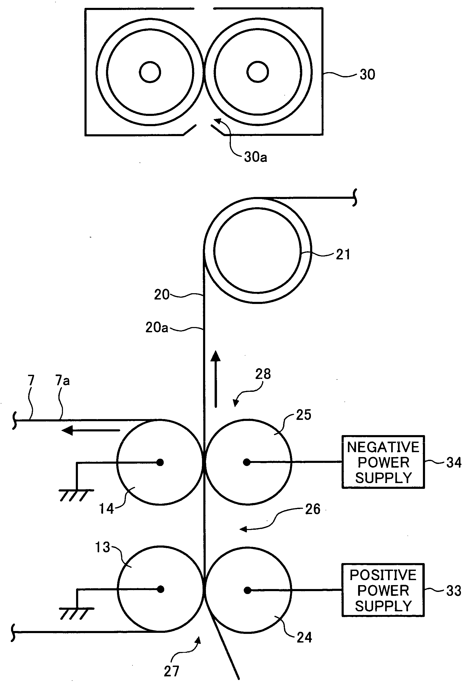
[0172] In this Experiment Example 1, we examined the relationship between the transfer currents applied to the application roller 24 of the upstream nip 27 and to the application roller 25 of the downstream nip 28. In this experiment example, conditions other than the transfer current applied to the application rollers 24 and 25 were such that retransfer would be prevented from occurring (see the other experiment examples). When the color toner image on the first intermediate transfer belt 7 was transferred to the second intermediate transfer belt 20, a transfer current of +20 μA was applied to the application roller 24 of the upstream nip 27, and the color toner image on the first intermediate transfer belt 7 was subjected to the action of electrostatic attraction and transferred to the second intermediate transfer belt 20.

[0173] Two-sided transfer to the recording medium S was performed by applying a transfer current of +50 μA to the application roller 24 of the upstream nip 27 a...

experiment example 2

[0177] In this Experiment Example 2, in addition to what was done in Experiment Example 1, we examined the relationship between the thickness of the recording medium S and the transfer current applied to the application rollers 24 and 25.

[0178] This color printer 100 is provided with means for varying the transfer current applied to the application rollers 24 and 25 according to the thickness of the recording medium S. This means is a function executed by the controller according to a program preloaded on a ROM or the like, on the basis of detection results from a paper thickness detector that detects the thickness of the recording medium S. Examples of the paper thickness detector that detects the thickness of the recording medium S include various sensors provided to the site of the resist rollers, such as a sensor for sensing the gap of the roller pair constituting the resist rollers 19 while the recording medium S passes through, and a strain sensor for sensing the pressing for...

experiment example 3

[0184] In this Experiment Example 3, we examined the relationship between the width of the nip of the electroconductive rollers 13 and 24 of the upstream nip 27 (nip width), and the width of the nip of the electroconductive rollers 14 and 25 of the downstream nip 28 (nip width). In this example, conditions other than the nip width were such that retransfer could be prevented (see the other experiment examples).

[0185] Two-sided transfer to the recording medium S was performed with the nip width of the upstream nip 27 set to 4 mm and the nip width of the downstream nip 28 set to 1 mm, after which the images were fixed by the fixing apparatus 30. The fixed images were examined, which confirmed that no retransfer of the color toner images from the recording medium S to the first intermediate transfer belt 7 occurred in the downstream nip 28.

[0186] The outer peripheral surface of the pairs of electroconductive rollers 24 and 13 (25 and 14) that constitute the upstream nip 27 and the do...


PUM


Abstract

An image forming apparatus for recording on two sides in a single pass, with which the transfer of a toner image onto one side of a recording medium and the transfer of a toner image onto the other side can both be performed under optimal conditions, which results in an increase in image quality. Contact-type transfer rollers are used as secondary and tertiary transfer means, so unlike with a transfer charger (a non-contact type of transfer means), there is no discharge product. A toner image that has been once transferred from an image support onto a recording medium is prevented from being retransferred back onto the image support, and a toner image that has been transferred onto the recording medium by the action of a first transfer member is prevented from being retransferred to the image support when a toner image is transferred onto the recording medium by the action of a second transfer member.

Description

BACKGROUND OF THE INVENTION [0001] 1. Field of the Invention [0002] The present invention relates to an image forming apparatus for recording on two sides in a single pass, with which a toner image can be formed on both sides of a recording medium in a single paper pass. [0003] 2. Description of the Related Art [0004] Some known copiers, printers, facsimile devices, and other such image forming apparatus are designed with a two-side recording function, whereby images are formed on both sides of a recording medium such as paper. With such conventional image forming apparatus capable of recording on two sides, the standard approach is to employ a system whereby the image (visualized image such as toner image) from one side of an original formed on an image support such as a photosensitive member is first transferred to and fixed on the surface of paper, and then this paper is turned over by an inversion path or the like and fed through the machine again, so that the image (visualized ...

Claims


Application Information

Patent Timeline
IPC IPC(8): G03G15/16
CPCG03G2215/1614G03G15/167
Inventor SOHMIYA, NORIMASATAGUMA, KENICHIKANEKO, CHIEMI
Owner RICOH KK
Why Eureka
Try Eureka