Plug detector for an electrical test instrument

Inactive Publication Date: 2005-02-17
JOHN FLUKE MFG CO INC
View PDF5 Cites 11 Cited by
  • Summary
  • Abstract
  • Description
  • Claims
  • Application Information

AI Technical Summary

Benefits of technology

[0005] In accordance with the present invention, a plug detector for an electronic test instrument includes an isolation transformer interposed between a jack socket and a plug detection circuit. The jack socket includes a split jack arrangement in which two halves of a jack socket are electrically connected together when a jack plug is inserted into the socket, and are otherwise electrically isolated from each other. The two halves of the jack socket are connected to opposite ends of a primary winding of the isol

Problems solved by technology

However, operator mistakes still can happen, and a wrong test lead plugged into a wrong jack can range from incorrect measurement results to catastrophic failure of the

Method used


Image

  • Plug detector for an electrical test instrument
  • Plug detector for an electrical test instrument

Examples


Embodiment Construction

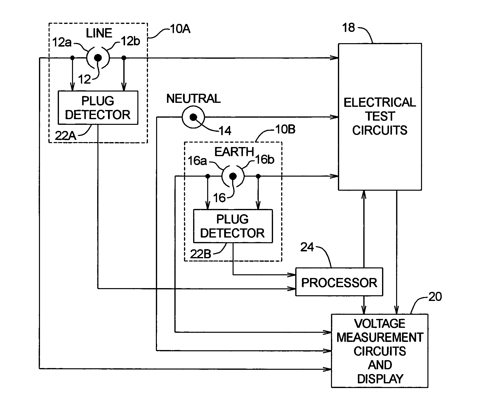
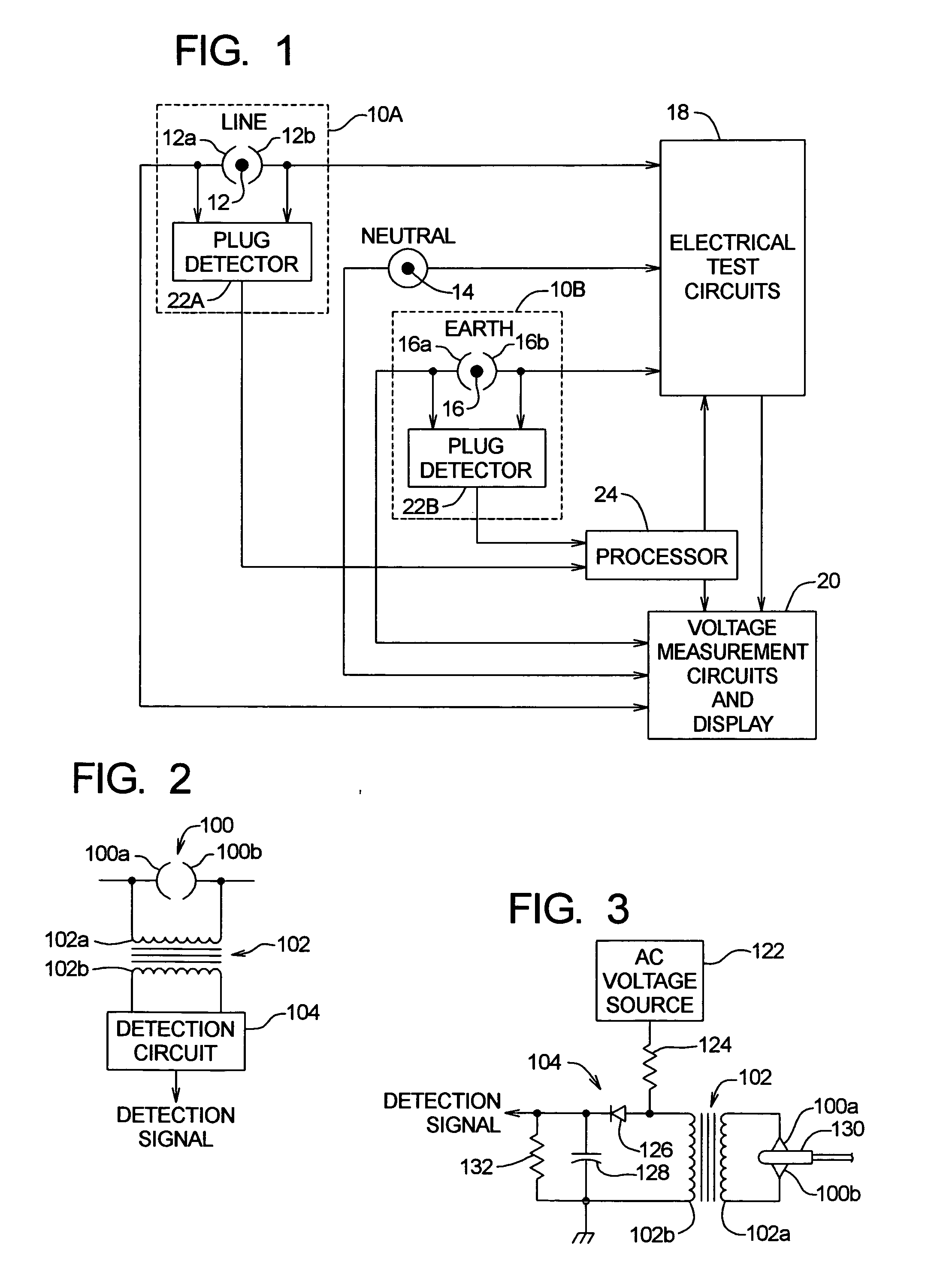
[0010] Referring to FIG. 1 of the drawings, there is shown a schematic representation of an exemplary electronic test instrument for testing electrical circuits, the test instrument including plug detector circuits 10A and 10B. The test instrument includes a LINE input jack socket 12, a NEUTRAL input jack socket 14, and an EARTH input jack socket 16. Input jack sockets 12, 14, and 16 are connected to provide inputs respectively to electrical test circuits 18 and voltage measurement circuits and display 20.

[0011] While the details of electrical test circuits 18 are not shown, such circuits are well known to those having ordinary skill in the art and typically include circuits for testing electrical circuits having residual current devices (RCDs) and measuring so-called loop currents and voltages (e.g., line-neutral and line-earth loops) found in three-phase power systems. Likewise, the details of the voltage measurements and display circuits 20 are not shown and are well known to th...


PUM


Abstract

A plug detector for an electronic test instrument includes an isolation transformer interposed between a jack socket and a plug detection circuit. The jack socket includes a split jack arrangement in which two halves of a jack socket are connected to opposite ends of a primary winding of the isolation transformer. When the primary winding is loaded due to the insertion of a jack plug, the primary winding is shorted and the impedance of a secondary winding changes. The detection circuit detects the change in impedance in the secondary winding and generates a detection signal to indicate plug detection.

Description

BACKGROUND OF THE INVENTION [0001] This invention relates generally to electrical test instruments, and in particular to detecting whether test leads are plugged into such instruments. [0002] Sophisticated electronic test instruments for testing electrical circuits are capable of performing multiple functions, including not only measuring several ranges of ac and dc voltages, but sourcing current and voltage in order to measure resistance and perform other testing of electrical circuits or multiple-phase power systems. It is common to provide different test leads with different types of connectors to an attempt to ensure that test leads and inputs to the test instrument are properly matched up for a particular test. However, operator mistakes still can happen, and a wrong test lead plugged into a wrong jack can range from incorrect measurement results to catastrophic failure of the instrument caused by an arc blast, and perhaps even to injury or death. [0003] It is desirable for an ...

Claims


Application Information

Patent Timeline
IPC IPC(8): G01R31/04
CPCG01R31/045G01R31/69
Inventor HARDY, WILLIAM DEAN
Owner JOHN FLUKE MFG CO INC
Why Eureka
Try Eureka