Current fuse and method of making the current fuse

a current fuse and current technology, applied in the direction of circuit-breaking switches, soldering devices, manufacturing tools, etc., can solve the problems of deterioration of quality, deterioration of solderability, and harm to the human body

Inactive Publication Date: 2005-02-17
KOA CORP
View PDF10 Cites 29 Cited by
  • Summary
  • Abstract
  • Description
  • Claims
  • Application Information

AI Technical Summary

Benefits of technology

[0011] The present invention has been developed in view of the above-described problems, and aims to provide a current fuse, which has solderability suitable for electronic equipment and electronic components, and does not have an adverse influence on the environment including the human body, and a method of manufacturing the current fuse.

Problems solved by technology

On the other hand, tin-lead solder is essential for fabricating or assembling electronic equipment; however, it contains lead which is harmful to the human body and the like.
Such temperature degrades plating on the surface of metallic caps, resulting in deterioration of solderability when mounting a fuse on a substrate.
That solder used in the interior of component causes a problem of deterioration of quality, such as break of a fuse element when the solder within each component melts in a reflow process when mounting the fuse on the substrate.

Method used


Image

  • Current fuse and method of making the current fuse
  • Current fuse and method of making the current fuse
  • Current fuse and method of making the current fuse

Examples


Embodiment Construction

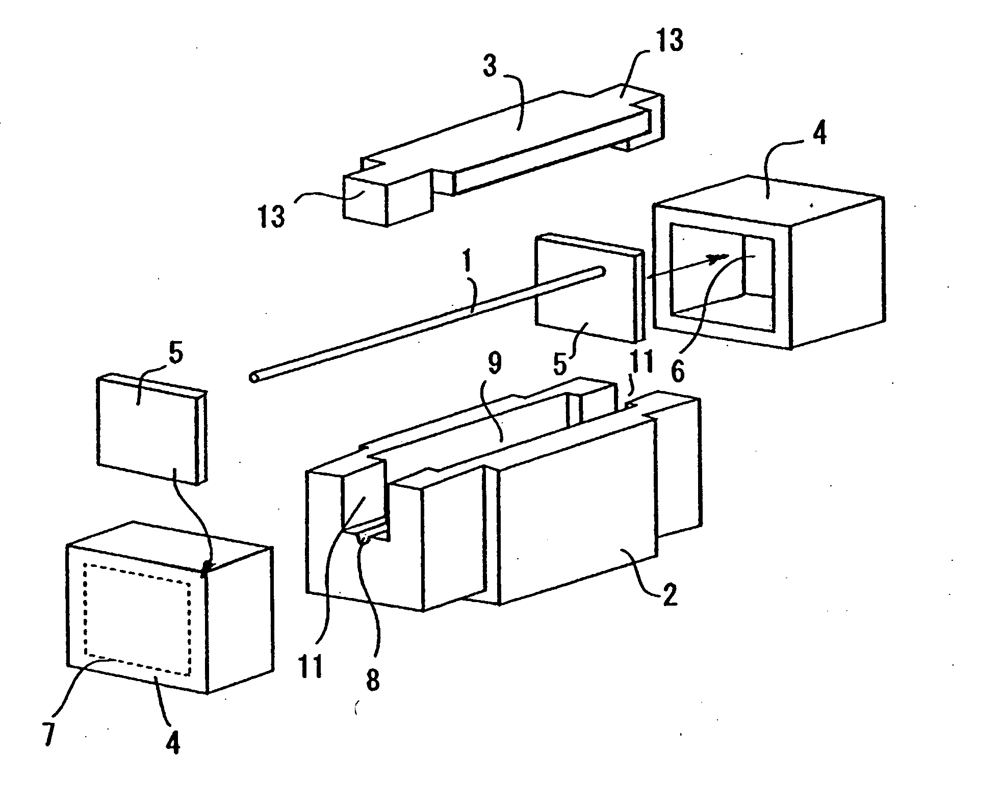
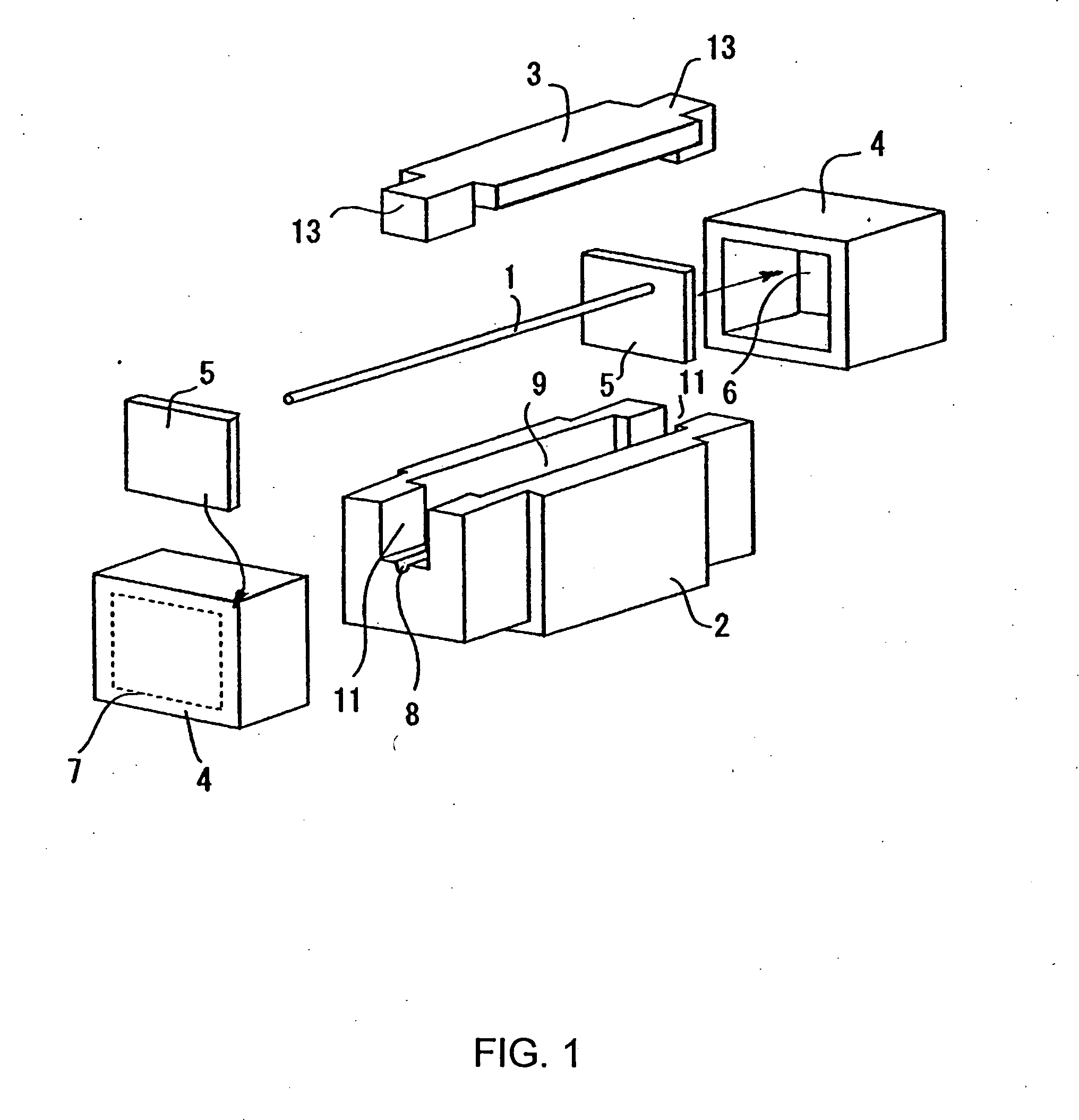
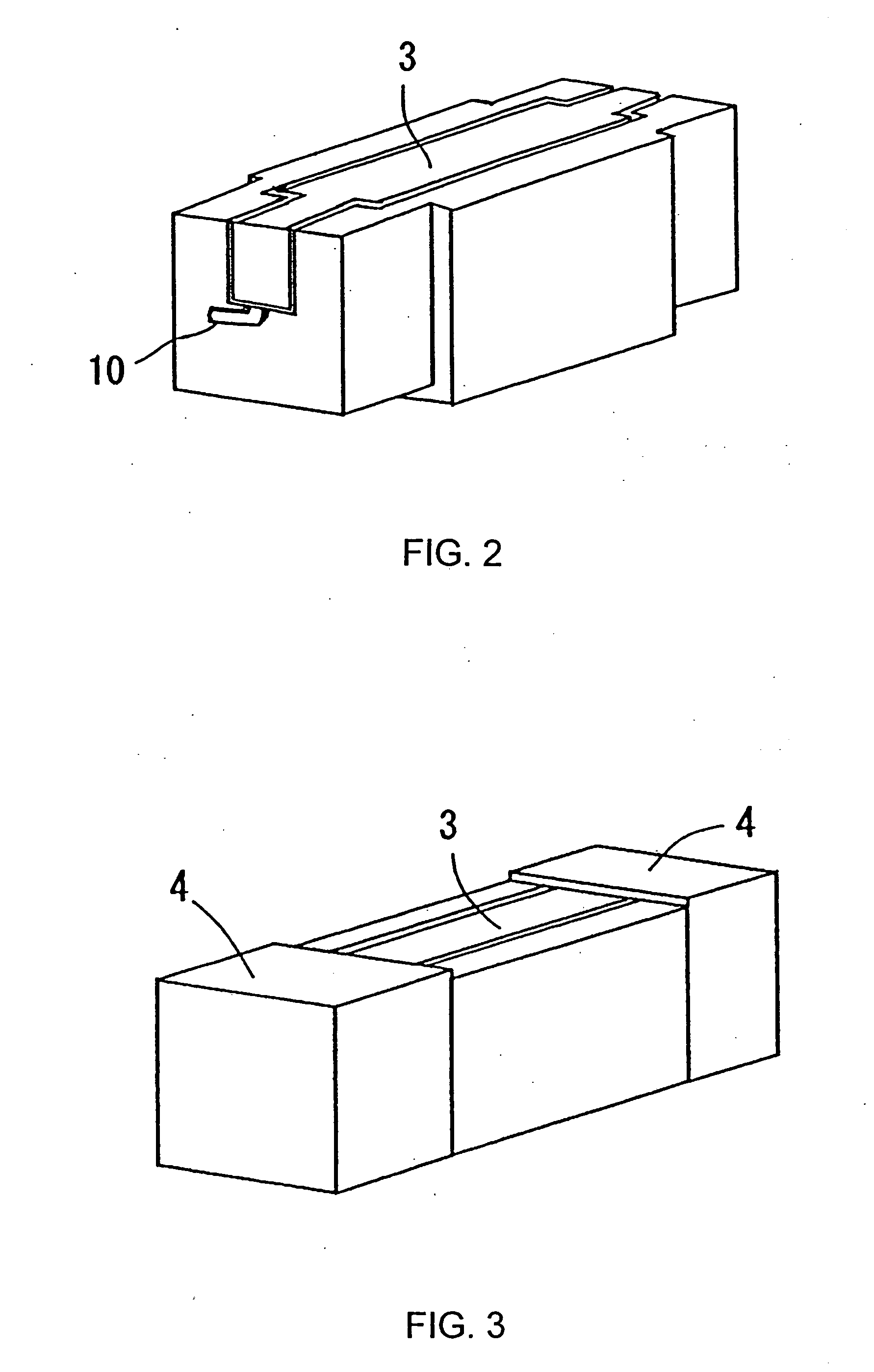
[0026] An embodiment of the present invention is described in detail forthwith while referencing the attached drawings. FIG. 1 is an exploded block diagram of a chip-type fuse according to the embodiment of the present invention. The chip-type fuse shown in the drawing is configured by stretching a fuse in a hollow space of a ceramic substrate. This substrate is formed by attaching a ceramic lid 3 to a ceramic casing main body 2.

[0027] At the center of the casing main body 2, an opening 9 which is opening upward is provided. At both ends of the casing main body 2, concave portions 11 communicating with that opening 9 are provided.

[0028] On the respective bottoms of the concave portions 11, a single-thread groove 8 is formed. A soluble fuse wire (fuse element) 1 is aligned with this groove 8, and stretching across the opening 9.

[0029] Note that when stretching the fuse wire 1 between the concave portions 11, a constant tension is applied to that fuse wire 1. In this case, the fuse...


PUM

PropertyMeasurementUnit
weightaaaaaaaaaa
temperatureaaaaaaaaaa
liquidaaaaaaaaaa

Abstract

In order to provide a current fuse with high solderability without containing harmful materials, solder chips containing 30 to 60 percent by weight of zinc, 0.1 to 2 percent by weight of copper, 0.1 to 1 percent by weight of nickel, and the remainder percent by weight being tin, or further containing 0.01 to 0.5 percent by weight of aluminum are inserted into the interior of the electrodes before pressing the electrodes into the ends of the substrate of the fuse, the exterior of the electrodes is heated to melt the solder chips, thereby connecting between the electrodes and the fuse wire.

Description

BACKGROUND OF THE INVENTION [0001] 1. Field of the Invention [0002] The present invention relates to a lead-free current fuse, which is suitable for electronic equipment and electronic components, for example, and a method of making the current fuse. [0003] 2. Description of the Related Art [0004] Various kinds of compact fuses, which are surface-mountable on a printed circuit board or the like, have been proposed. For example, a fuse in which a fuse element stretches in a hollow space within a rectangular case formed by attaching a ceramic casing main body and a lid has been disclosed in Japanese Patent Application Laid-Open No. 8-222117. [0005] In the case of this compact fuse, a fuse element and tin-lead solder, which has been adhered to the interior of metallic cap in advance, are soldered. [0006] On the other hand, tin-lead solder is essential for fabricating or assembling electronic equipment; however, it contains lead which is harmful to the human body and the like. Therefore...

Claims


Application Information

Patent Timeline
Patent Type & Authority Applications(United States)
IPC IPC(8): B23K35/26B23K35/28C22C9/00C22C13/00C22C18/00H01H69/02H01H85/041H01H85/143H01H85/157
CPCB23K35/262B23K35/282C22C13/00H01H85/0418H01H85/157H05K2203/043H05K3/143H05K3/26H05K3/3484H05K3/3489H05K3/1216H05K3/3485
Inventor KOBAYASHI, SATORUKATO, KAZUYUKI
Owner KOA CORP
Why Eureka
Try Eureka