Ink jet print head, inkjet printer including the inkjet print head, and method of manufacturing inkjet print head

a technology of inkjet printer and inkjet printer, which is applied in the direction of printing and inking apparatus, etc., can solve the problems of reducing printing quality, uneven printing with streaks, and difficulty in putting such a related line printer described above into practical use, and achieve the effect of preventing a reduction in printing quality

Inactive Publication Date: 2005-02-17
SONY CORP
View PDF6 Cites 229 Cited by
  • Summary
  • Abstract
  • Description
  • Claims
  • Application Information

AI Technical Summary

Benefits of technology

[0021] In view of the above-described problems, it is an object of the present invention to provide an inkjet print head capable of preventing a reduction in printing quality due to displacement of a discharge nozzle, and stabilizing a landing position of discharged ink on a recording sheet, an inkjet print head including the inkjet print head, and a method for producing the inkjet print head.

Problems solved by technology

However, it is difficult to put such a related line printer described above into practical use because it has the following problems.
As a result, the color ink does not land on the proper position, thereby reducing printing quality.
Such a problem occurs due to the use of a structure comprising nozzles disposed in correspondence with the positions of the head chips.
Therefore, uneven printing with streaks occurs in a sheet transportation direction.
Accordingly, when a color print head is constructed by disposing head chip rows in correspondence with yellow, magenta, cyan, and black inks, the following problem occurs even if the precision with which the head chip corresponding to one color is positioned is increased as stated in, for example, Japanese Examined Patent Application Publication No. 7-115504.
That is, a positioning error in any of the head chip rows for the respective colors causes what is called registration to occur between the ink discharge nozzles for one color and those for another color.
This leads to a reduction in color reproducibility, resulting in a reduction in printing quality as described above.
This is because, if the cross-sectional shapes are wider from the inner side to the outer side of the print head, scattered ink is discharged, thereby reducing the landing precision of the ink on the recording sheet.

Method used


Image

  • Ink jet print head, inkjet printer including the inkjet print head, and method of manufacturing inkjet print head
  • Ink jet print head, inkjet printer including the inkjet print head, and method of manufacturing inkjet print head
  • Ink jet print head, inkjet printer including the inkjet print head, and method of manufacturing inkjet print head

Examples


first embodiment

[0056] (First Embodiment)

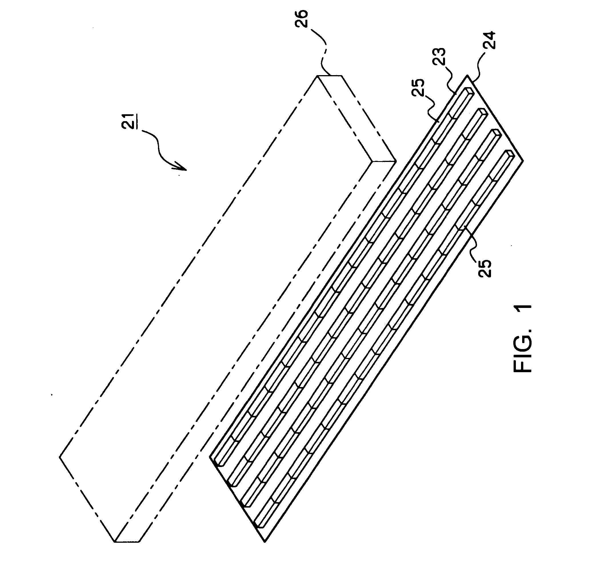
[0057] As shown in FIG. 1, an inkjet print head (hereinafter simply referred to as “head”) 21 which performs line printing and has a plurality of recording elements disposed in a print width direction for discharging ink from discharge nozzles is formed of an electroformed layer formed of nickel or a material comprising nickel. The head 21 comprises a nozzle sheet 23, a plurality of head chips (substrate members) 25, and a member 26. In the nozzle sheet 23, four discharge nozzle rows for respective colors, yellow, magenta, cyan, and black, are disposed in correspondence with printing operations using the colors yellow, magenta, cyan, and black and in substantially straight lines in a direction in which the rows traverse a sheet (that is, print width direction). In correspondence with the discharge nozzle rows for the respective colors, the head chips 25 are successively disposed on the nozzle sheet 23 in straight lines and are affixed to the nozzle sheet 23....

second embodiment

[0088] (Second Embodiment)

[0089] In the first embodiment, four discharge nozzle rows for the respective ink colors are formed in the nozzle sheet 23 substantially in straight lines and in the direction in which they traverse a sheet (print width direction), and the head chips 25 are disposed on the nozzle sheet in rows in substantially straight lines in correspondence with the discharge nozzles. In this embodiment, discharge nozzle rows for respective colors are disposed in a nozzle sheet so that discharge nozzles in predetermined numbers are in staggered arrangements, and head chips 25 are disposed on the nozzle sheet in staggered arrangements in correspondence with the discharge nozzles. The other structural features are the same as those of the first embodiment, and, thus, will not be described below. In addition, the method for producing the nozzle sheet is the same, and, thus, will not be described below either.

[0090] As shown in FIG. 7, a head 21 is formed of an electroformed...

third embodiment

[0095] (Third Embodiment)

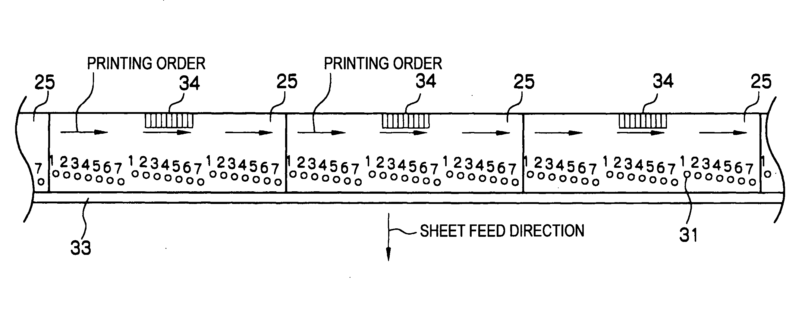
[0096] In the second embodiment, four discharge nozzle rows for the respective colors are disposed in the nozzle sheet 23 so that discharge nozzles in predetermined numbers are in the staggered arrangements with the distance between each discharge nozzle being the same in the direction in which the discharge nozzle rows traverse the sheet (print width direction), and the head chips 25 are disposed on the nozzle sheet 23 in the staggered arrangements in correspondence with the discharge nozzle rows. In this embodiment, further, discharge nozzle rows are disposed so that each set of discharge nozzles partly overlaps another set of discharge nozzles in a sheet transportation direction (recording medium transportation direction).

[0097]FIG. 9 shows the arrangement of head chips 25 in the embodiment, and is an enlarged view of a portion from the sheet 14 side in FIG. 12. As shown in FIG. 9, the discharge nozzles of the discharge nozzle rows for respective colors ...


PUM


Abstract

An inkjet print head includes one nozzle sheet (23) and a plurality of head chips (25) including a plurality of heaters. The nozzle sheet (23) is formed of an electroformed metal layer made of nickel or a material comprising nickel, and has discharge nozzle rows for respective colors disposed so that the discharge nozzles are in staggered arrangements and so that each set of discharge nozzles partly overlaps another set of discharge nozzles in a sheet-feed direction. The head chips are positioned at and affixed to a growth surface side of the nozzle sheet (23) in staggered arrangements so that the positions of the discharge nozzles and the positions of the heaters correspond to each other. Accordingly, reduction in printing quality caused by displacement of any of the discharge nozzles is prevented from occurring, and landing positions of discharged ink on a recording sheet are stabilized.

Description

TECHNICAL FIELD [0001] The present invention relates to an inkjet print head capable of full color printing and having a plurality of recording elements disposed in a print width direction, an inkjet printer including the inkjet print head, and a method for producing the inkjet print head. BACKGROUND ART [0002] In recent years, a demand for higher printing speed is drawing attention to an inkjet printer performing line printing (hereinafter may simply be referred to as “line printer”). The line printer can print a predetermined image in color without moving a print head having discharge nozzles by selectively causing ink drops to fly from the discharge nozzles onto a recording sheet while transporting the recording sheet. Rows of the discharge nozzles provided over a print width of the recording sheet are successively disposed for respective colors in a direction substantially perpendicular to a recording sheet transportation direction. [0003] Of inkjet printers as that described ab...

Claims


Application Information

Patent Timeline
Patent Type & Authority Applications(United States)
IPC IPC(8): B41J2/05B41J2/14B41J2/145B41J2/16
CPCB41J2/14024B41J2/1433B41J2/145B41J2202/20B41J2/1625B41J2202/19B41J2/162
Inventor ANDO, MAKOTOTOKUNAGA, HIROSHINAKAMURA, ATSUSHIKAYABA, SHINJIHORII, SHINICHI
Owner SONY CORP
Why Eureka
Try Eureka