Optical disk apparatus and computer readable recording medium storing program

Inactive Publication Date: 2005-02-17
YAMAHA CORP
View PDF12 Cites 3 Cited by
  • Summary
  • Abstract
  • Description
  • Claims
  • Application Information

AI Technical Summary

Benefits of technology

The invention has been accomplished in view of such circumstances and aims at providing an optical disk apparatus capable of forming a high-quality image onto

Problems solved by technology

The image forming feature incorporated into an optical disk apparatus leads to a more complicated design of the optical disk apparatus, which resu

Method used


Image

  • Optical disk apparatus and computer readable recording medium storing program
  • Optical disk apparatus and computer readable recording medium storing program
  • Optical disk apparatus and computer readable recording medium storing program

Examples


Example

<First Embodiment>

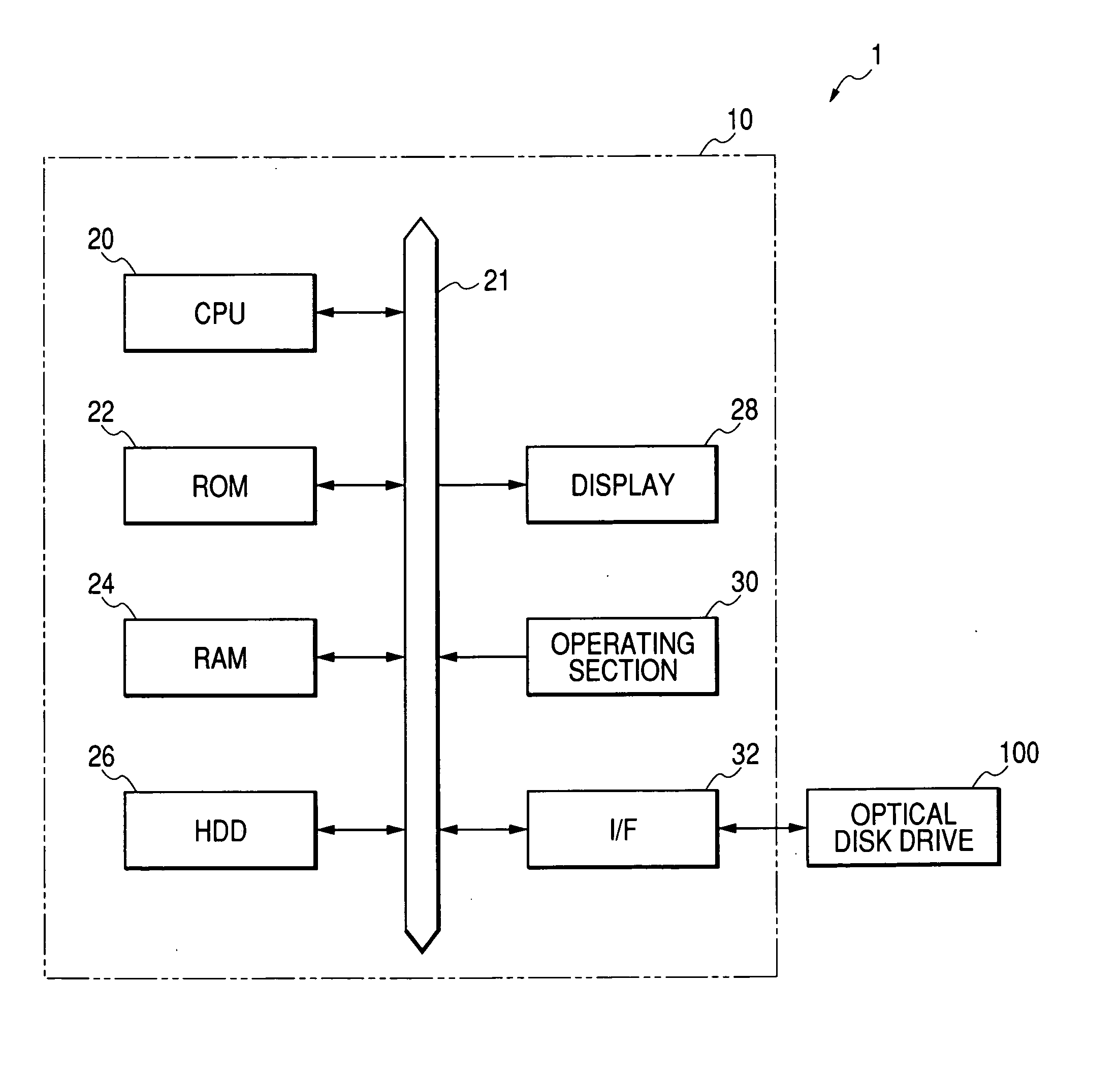
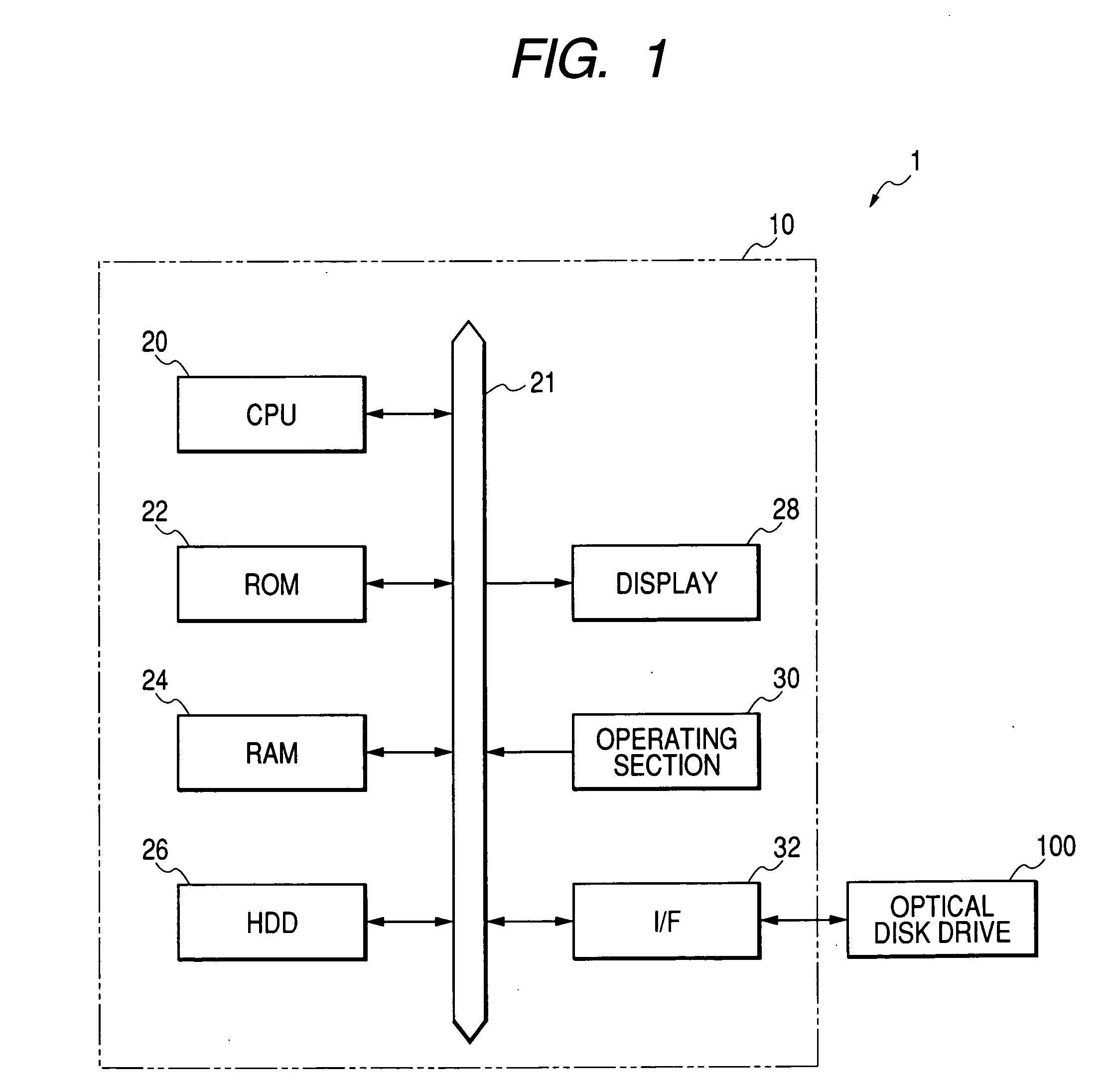
FIG. 1 is a block diagram showing the entire system configuration including an optical disk apparatus according to a first embodiment of the invention. As shown in FIG. 1, a system 1 comprises a host compute 10 connected to an optical disk apparatus 100 according to this embodiment. The host computer 100 comprises a CPU 20, a ROM 22, a RAM 24, an HDD (Hard Disk Drive) 26, a display 28, an operating section 30, and an interface 32 interconnected to each other via a bus 21. The HDD 26 stores an operating system as well as an application program for forming an image. The CPU 20 executes the application program to implement functional blocks mentioned later and processes image data and supplies the processed image data to the optical disk apparatus 100. In this embodiment, IDE (ATAP1) is used as a connection standard for the optical disk apparatus 100. The operating section 30 includes a keyboard and a mouse which inputs an operation instruction from the user.

&#x...

Example

<Second Embodiment>

While it is possible to form an image onto an optical disk in the first embodiment, the data recording configuration needed slight addition. The second embodiment which requires little change in the hardware configuration is described below.

FIG. 13 is a block diagram showing the configuration of the write signal generator 156 according to the second embodiment. As shown in FIG. 13, different from the configuration shown in FIG. 3, the second embodiment does not involve the discriminator l565, the time axis expander 1566, the gate circuit 1567 and the switch 1564. In the strategy circuit 1563a, correction in image formation is modified from the correction in data recording by the instruction information WS from the main controller 120. Other configuration of the second embodiment is the same as is in the first embodiment.

In the second embodiment, in case dot data is $D2 (hexadecimal notation), a white dot is specified. In case dot data is $82, a black dot ...


PUM


Abstract

An optical disk apparatus for forming an image on an optical disk according to dot data which defines density of dots of the image, the optical disk apparatus includes: a framing unit which makes a frame data by grouping a plurality of unit data, wherein when the dot data, the dot data are treated as the unit data; a pit forming unit which sequentially forms pits defined by a bit train signal of the frame data; a discrimination unit which determines whether the section in the frame data corresponding to the dot data is a predetermined value; and a gate unit which, in case the discrimination result by the discrimination unit is affirmative, supplies the bit train signal to the pit forming unit and, in case the discrimination result by the discrimination unit is negative, interrupts supply of the bit train signal to the pit forming unit.

Description

BACKGROUND OF THE INVENTION The present invention relates to an optical disk apparatus having a function of recording data onto an optical disk as well as a function of forming an image. Some of the optical disk apparatuss available in recent years have an image forming function of forming an image of a character or a figure in addition to a recording function of recording data such as audio data onto an optical disk including a CD-R (Compact Disc-Recordable) (for example, refer to the Japanese Patent Laid-Open No. 7530 / 1996). This type of optical disk apparatus irradiates with laser light a recording surface on which data is recorded to change the color of part of the recording surface by means of heat, thereby forming an image of a character or a figure. The image forming feature incorporated into an optical disk apparatus leads to a more complicated design of the optical disk apparatus, which results in an increase in device cost. A longer time required to form an image onto a...

Claims


Application Information

Patent Timeline
IPC IPC(8): G11B23/40G11B7/0037G11B7/0045G11B7/007G11B7/013G11B7/24094G11B7/24097G11B20/10G11B20/14H04N5/781
CPCG11B7/0045G11B20/1426G11B20/10009G11B7/24094
Inventor MORISHIMA, MORITO
Owner YAMAHA CORP
Why Eureka
Try Eureka