Securement mechanism including top loading tie down cleat assembly and locking member

Inactive Publication Date: 2005-02-17
SPORTRACK
View PDF5 Cites 55 Cited by
  • Summary
  • Abstract
  • Description
  • Claims
  • Application Information

AI Technical Summary

Benefits of technology

[0009] In a more preferred embodiment of the invention, the pin and actuating member threadingly engage one another such that rotation of the actuating member moves the pin and attached locking plate up and down. To prevent the pin from rotating at the same time the actuating member is rotated, it

Problems solved by technology

A problem with this approach is that a user has to physically remove a component to allow for installation of the cleat.
The end cap may be lost, become damaged, or be difficult to reinstall.
Moreover, the end of the rail

Method used


Image

  • Securement mechanism including top loading tie down cleat assembly and locking member
  • Securement mechanism including top loading tie down cleat assembly and locking member
  • Securement mechanism including top loading tie down cleat assembly and locking member

Examples


Embodiment Construction

[0027] Referring now to the drawings, preferred illustrative embodiments of the present invention are shown in detail. Although the drawings represent embodiments of the present invention, the drawings are not necessarily to scale and certain features may be exaggerated to better illustrate and explain the present invention. Further, the embodiments set forth herein are not intended to be exhaustive or otherwise limit or restrict the invention to the precise forms and configurations shown in the drawings and disclosed in the following detailed description.

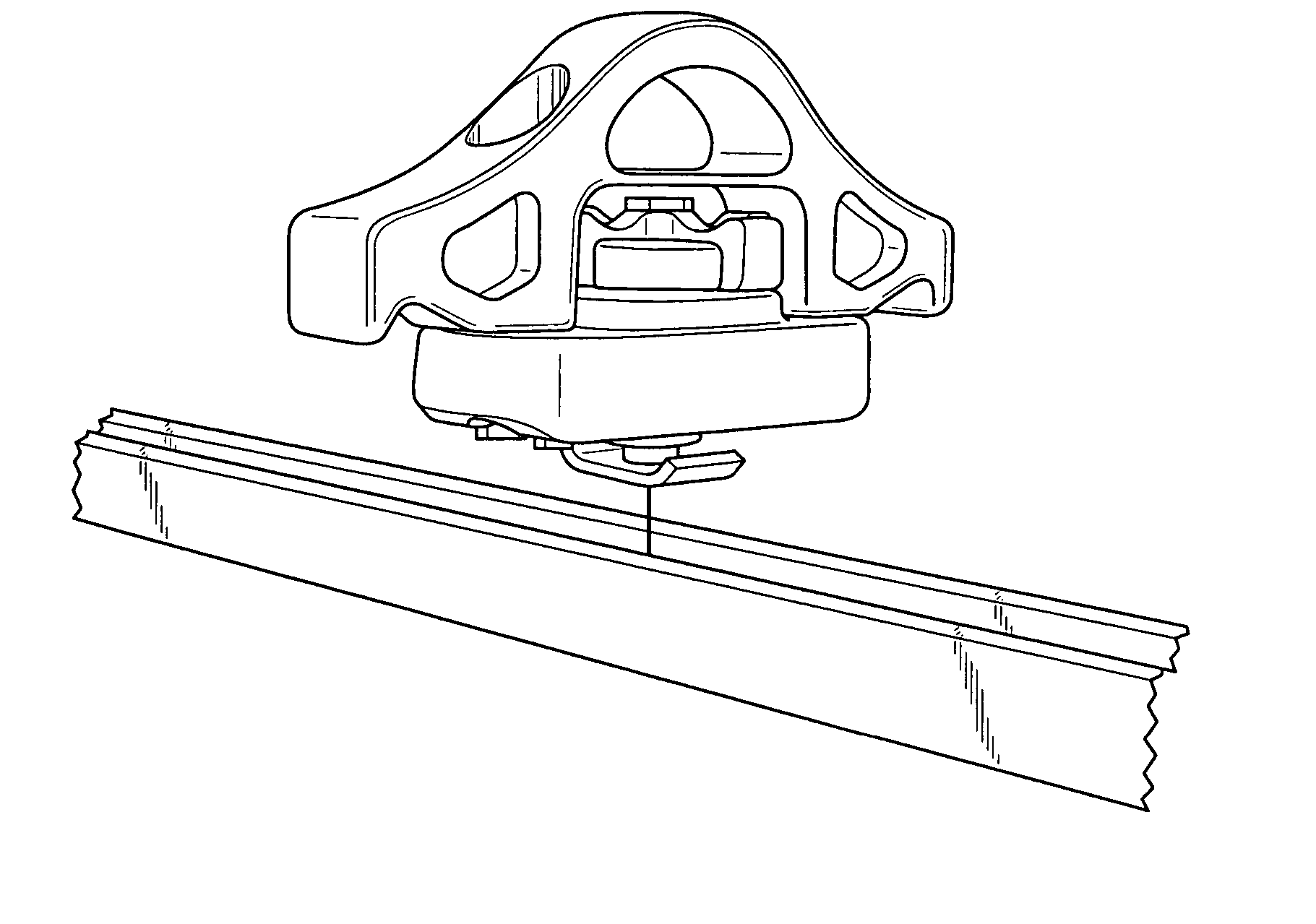
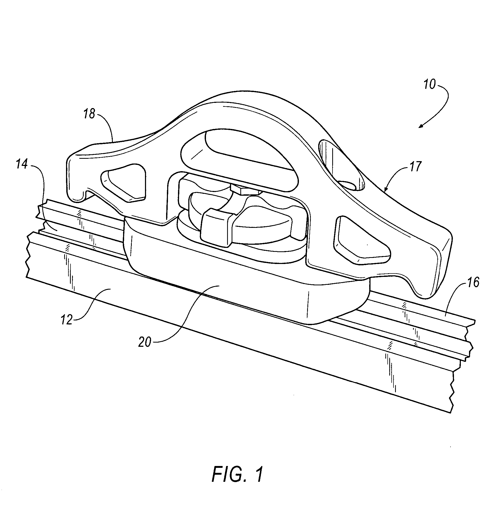
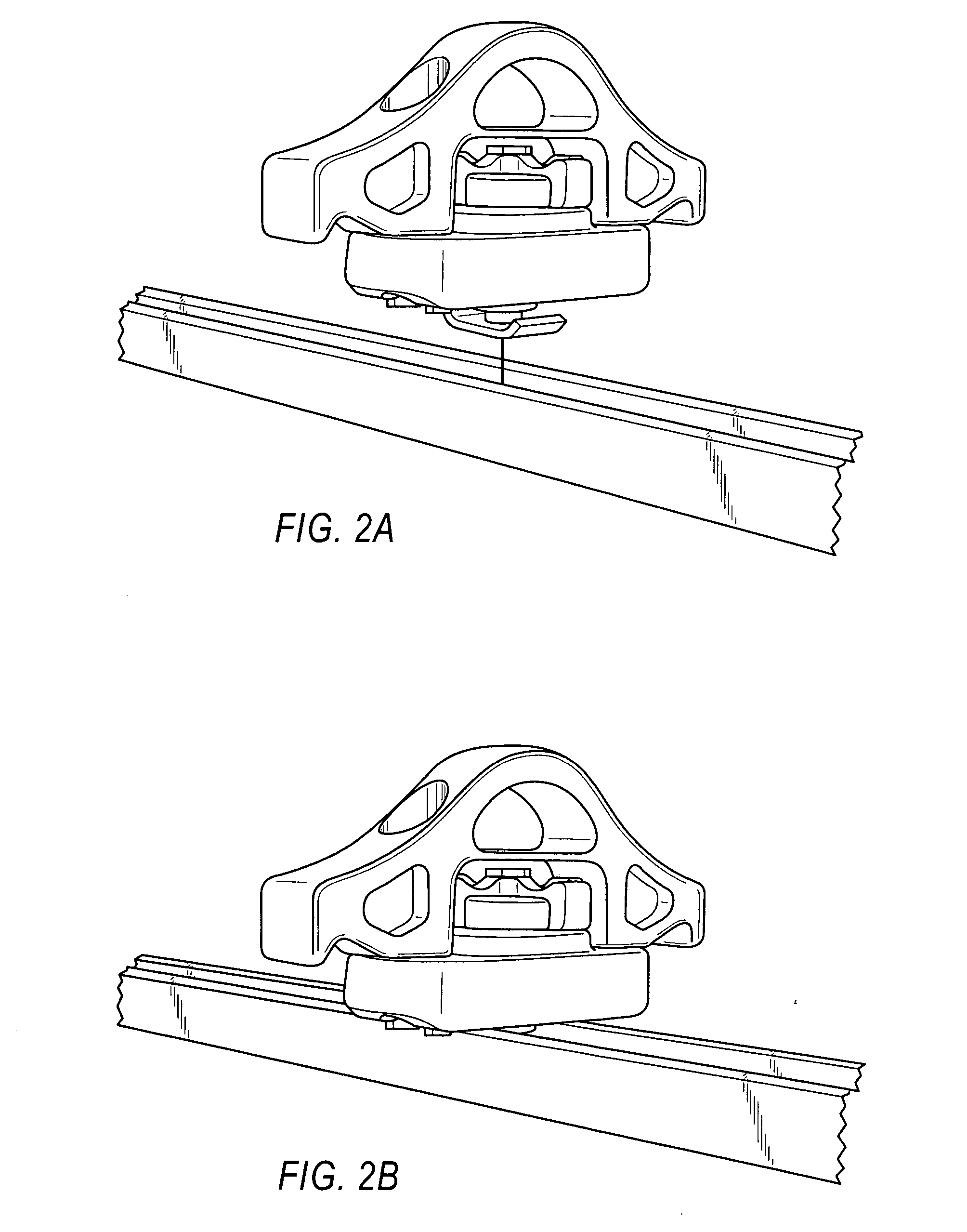
[0028] The present invention is directed to an innovative securement mechanism including a tie down cleat assembly 10 and mating component in the form of a locking member or rail 12, as shown in a first embodiment of FIGS. 1 through 7.

[0029] Rail 12 has a continuously extending channel 14 along its longitudinal length. The channel 14 of the rail 12 is defined by a web or bottom surface 50 disposed between opposing side rails 52, ...


PUM


Abstract

A securement mechanism includes a tie down cleat assembly for engagement with a mating component, the tie down cleat assembly including a pin, a lock plate adjacent one of the ends of the pin, and a housing with an aperture receiving the pin. An actuating member is operationally connected to the pin and causes selective movement of the pin and lock plate between a secured and unsecured orientation. The lock plate includes two dimensions, a first dimension permitting the lock plate to be inserted into a channel associated with the mating component and a second dimension permitting the securement of the mating component between the housing and locking plate. The pin and locking plate and preferably the housing all rotate as a single unit.

Description

CROSS-REFERENCE To RELATED APPLICATIONS [0001] This application claims the benefit of U.S. Provisional Application No. 60 / 463,291 filed Apr. 16, 2003, the entire contents of which are herein incorporated by reference.FIELD OF THE INVENTION [0002] The present invention is directed to an innovative tie down cleat assembly. The assembly is loaded into a rail or any vehicle surface and clamped into position. BACKGROUND OF THE INVENTION [0003] Tie down cleats are commonly used with rails having channels defined by side walls and a bottom surface disposed between the side walls. The top of each side wall typically has an inwardly extending leg disposed above the bottom surface. The tie down cleat is disposed along a rail with a portion of the tie down cleat including a lock plate being received within the channel, and movement selectively constrained through interaction of the cleat with at least a subset of the side walls, bottom surface, and legs. [0004] Typically, a tie down cleat is a...

Claims


Application Information

Patent Timeline
IPC IPC(8): B60P7/08B60R9/058F16B37/04
CPCB60P7/0815F16B37/045B60R9/058
Inventor CUNNINGHAM, MICHAEL P.HARBERTS, JOHN H.MILLER, DENNIS E.
Owner SPORTRACK
Why Eureka
Try Eureka